 1 Breaking ground. The diggers doing the digging... I wish. |
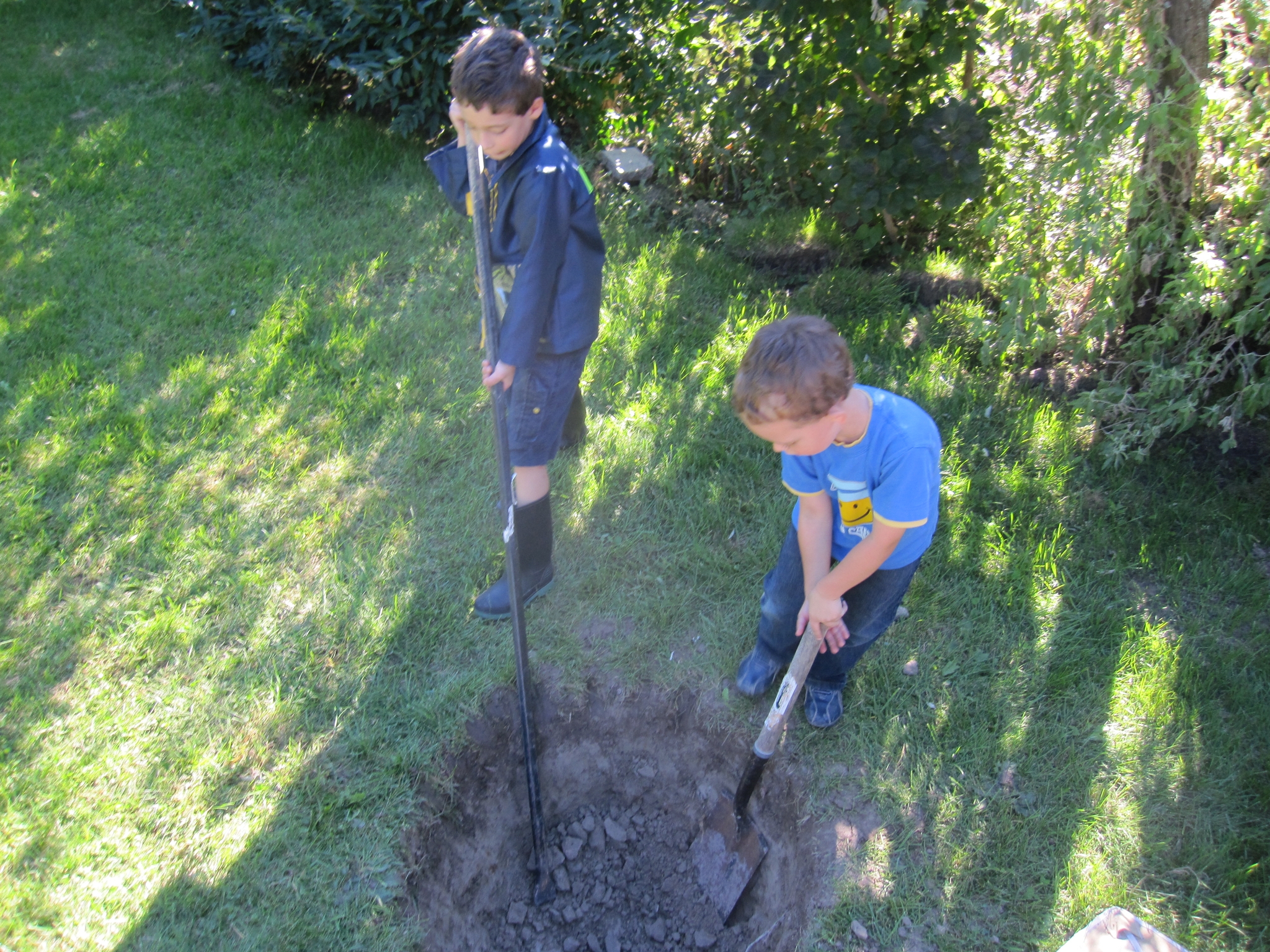
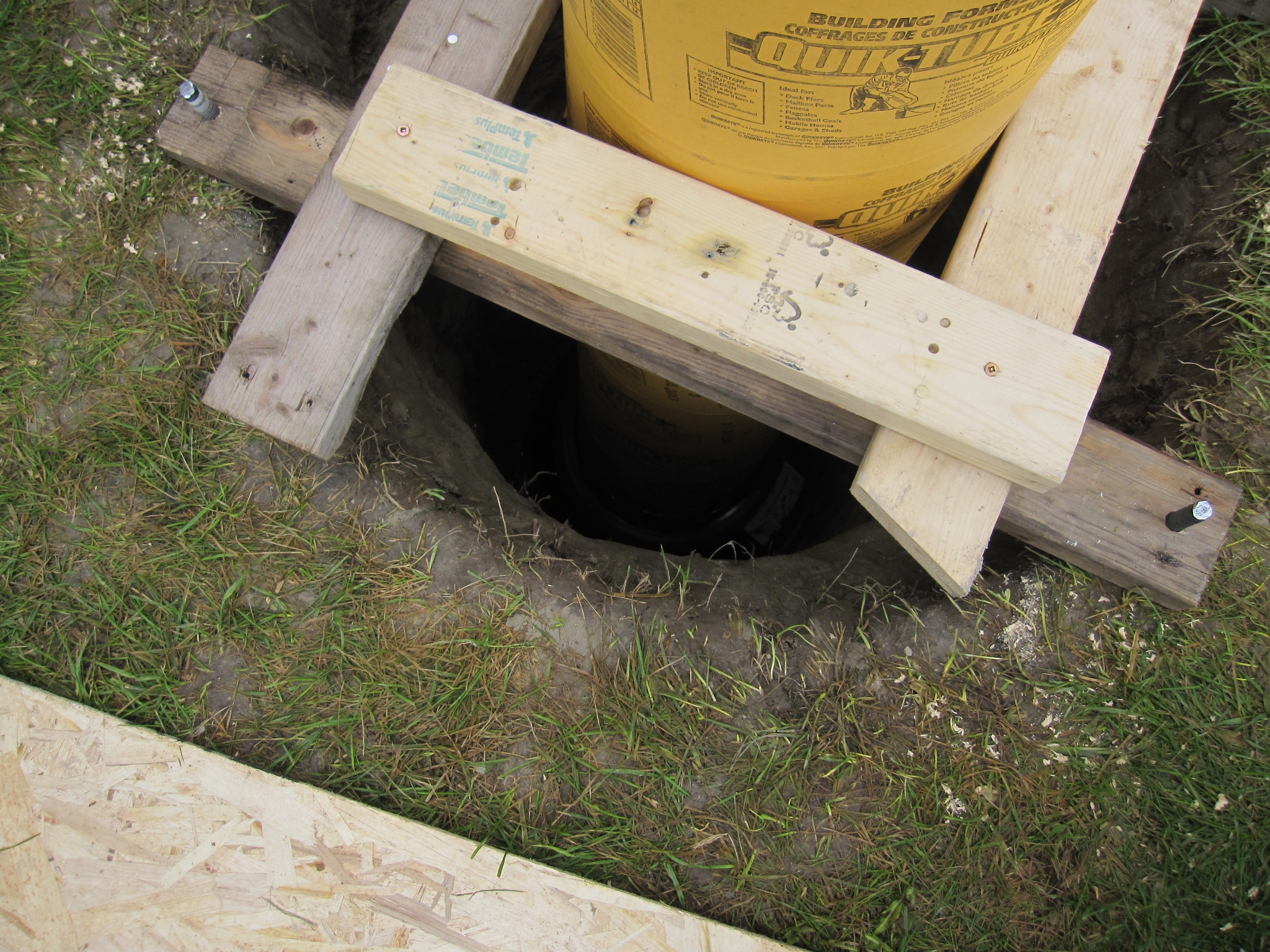
 2 Deep hole - 5 ft deep in rock hard clay. |
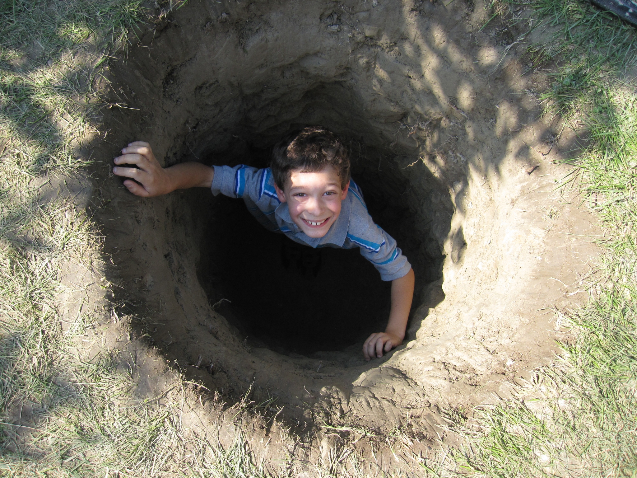 3 Both wanted a turn to be in the hole. |
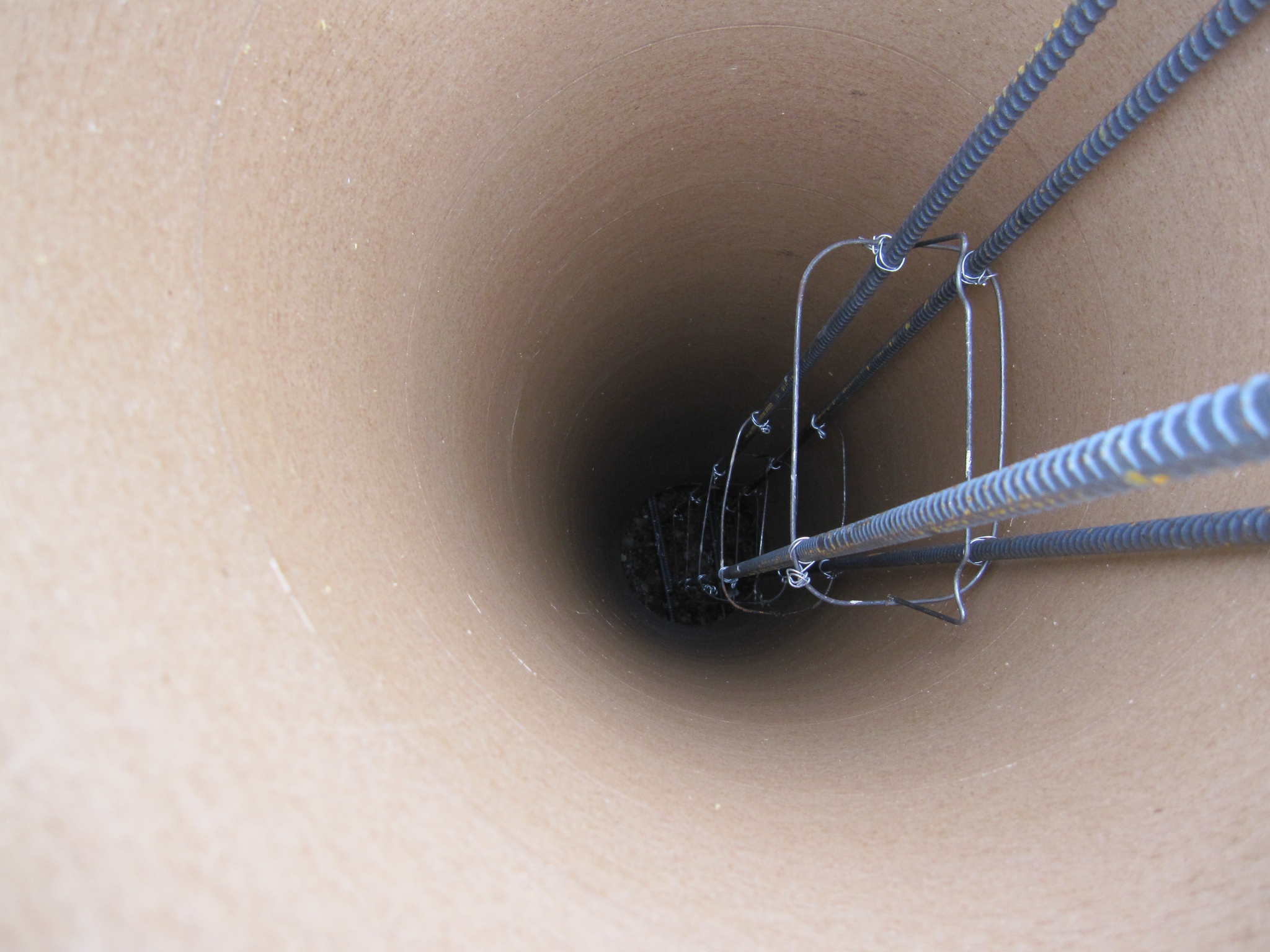
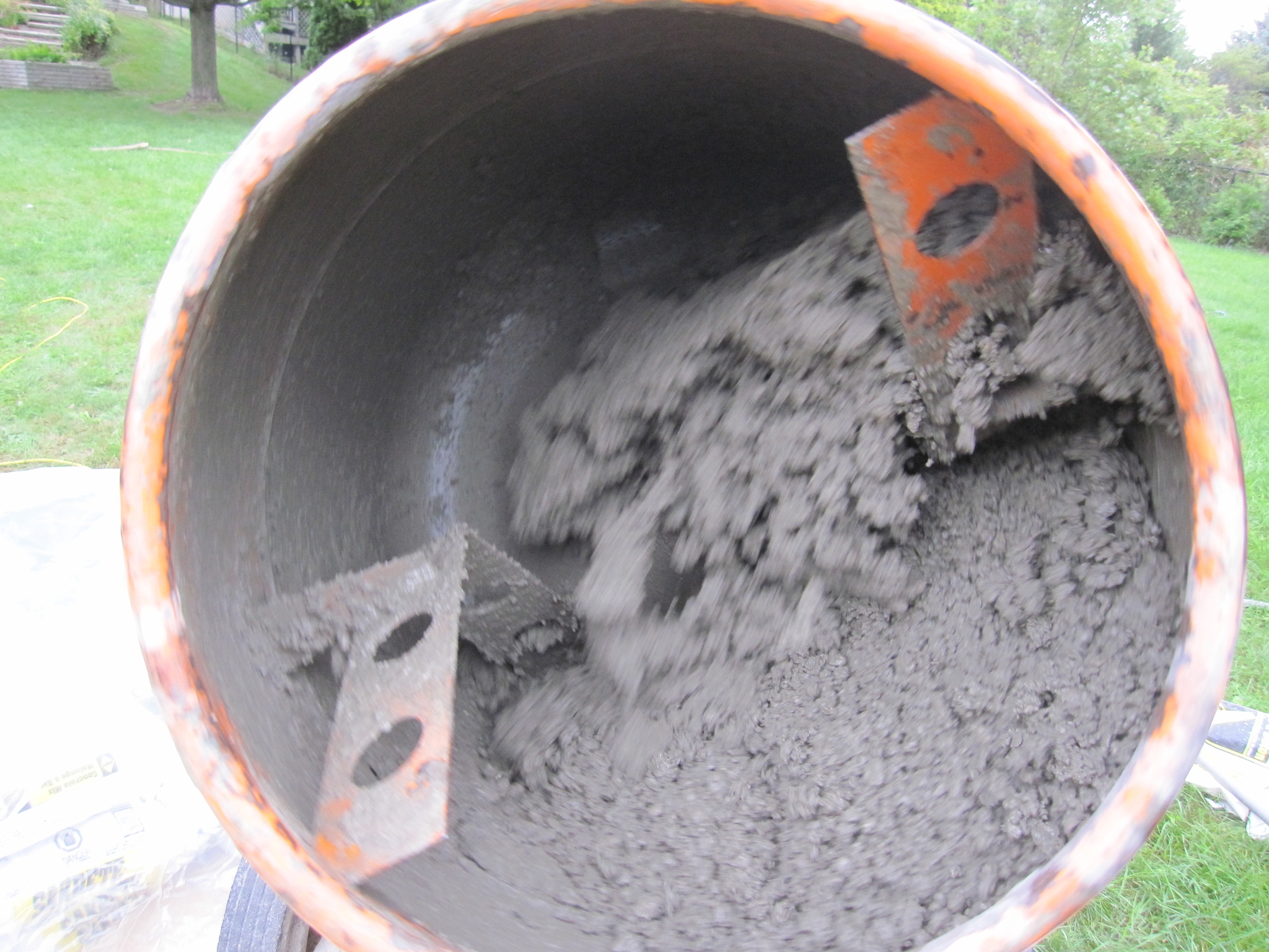
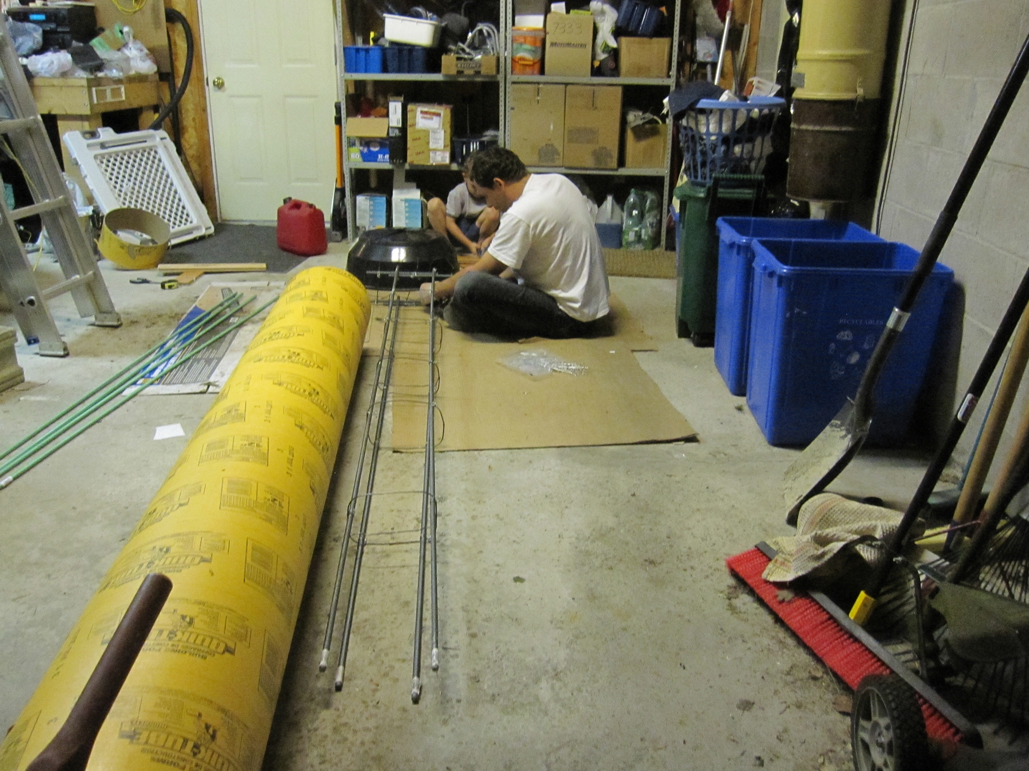 4 Can't have too much rebar. |
 5 The footing to keep the pier from moving (side to side, but particulraly up/down due to frost/frozen earth pushing up). |
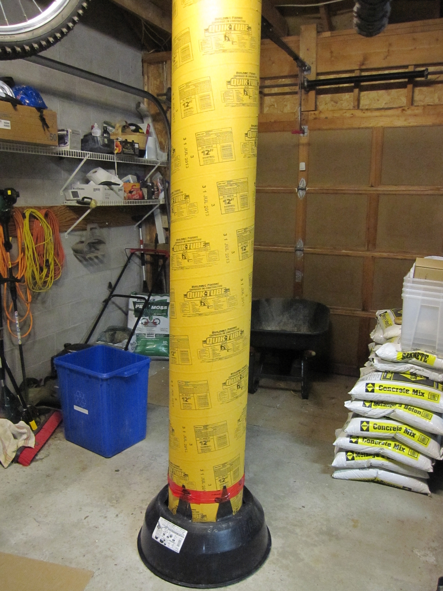
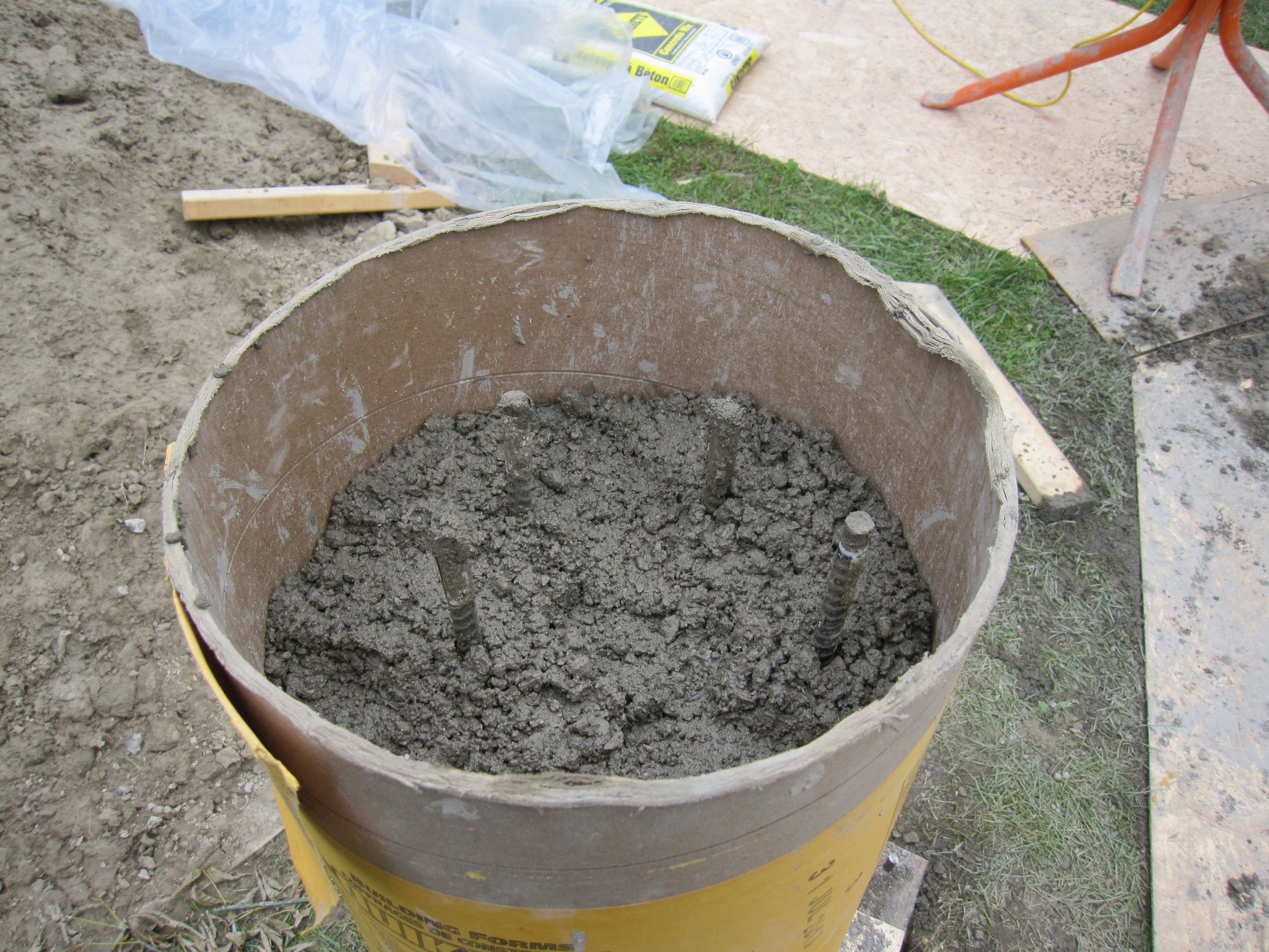
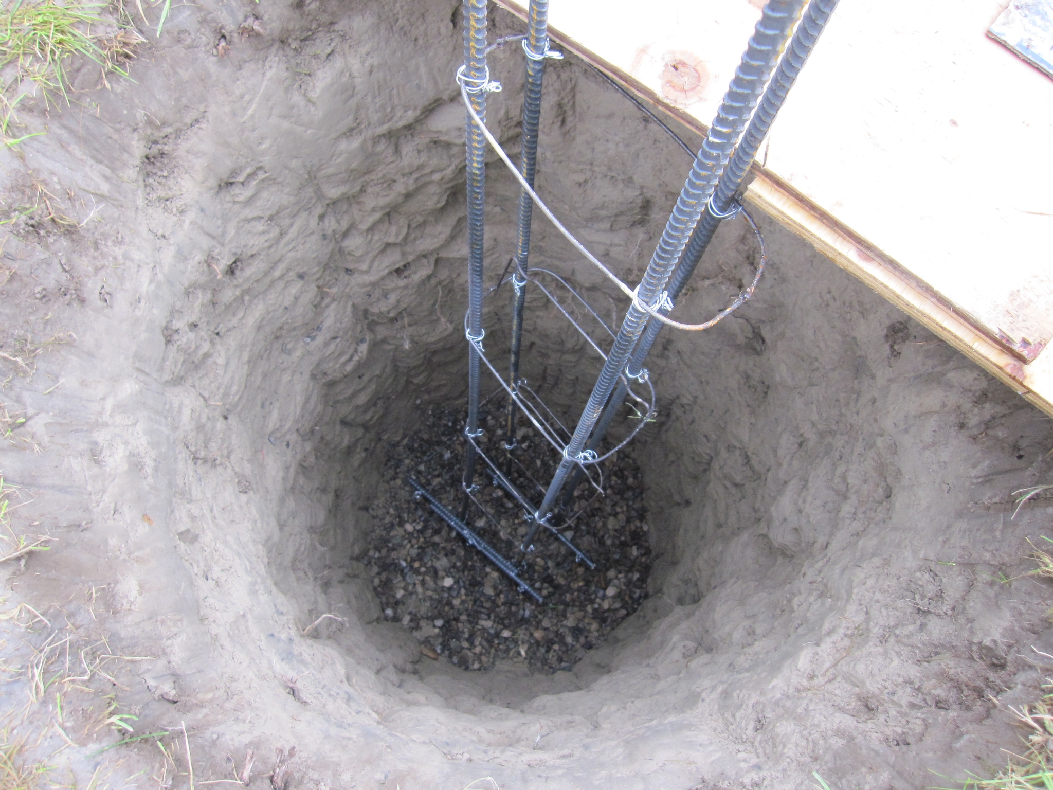 6 The 8ft rebar will be positioned as displayed here with about 4 inches of gravel at the buttom. |
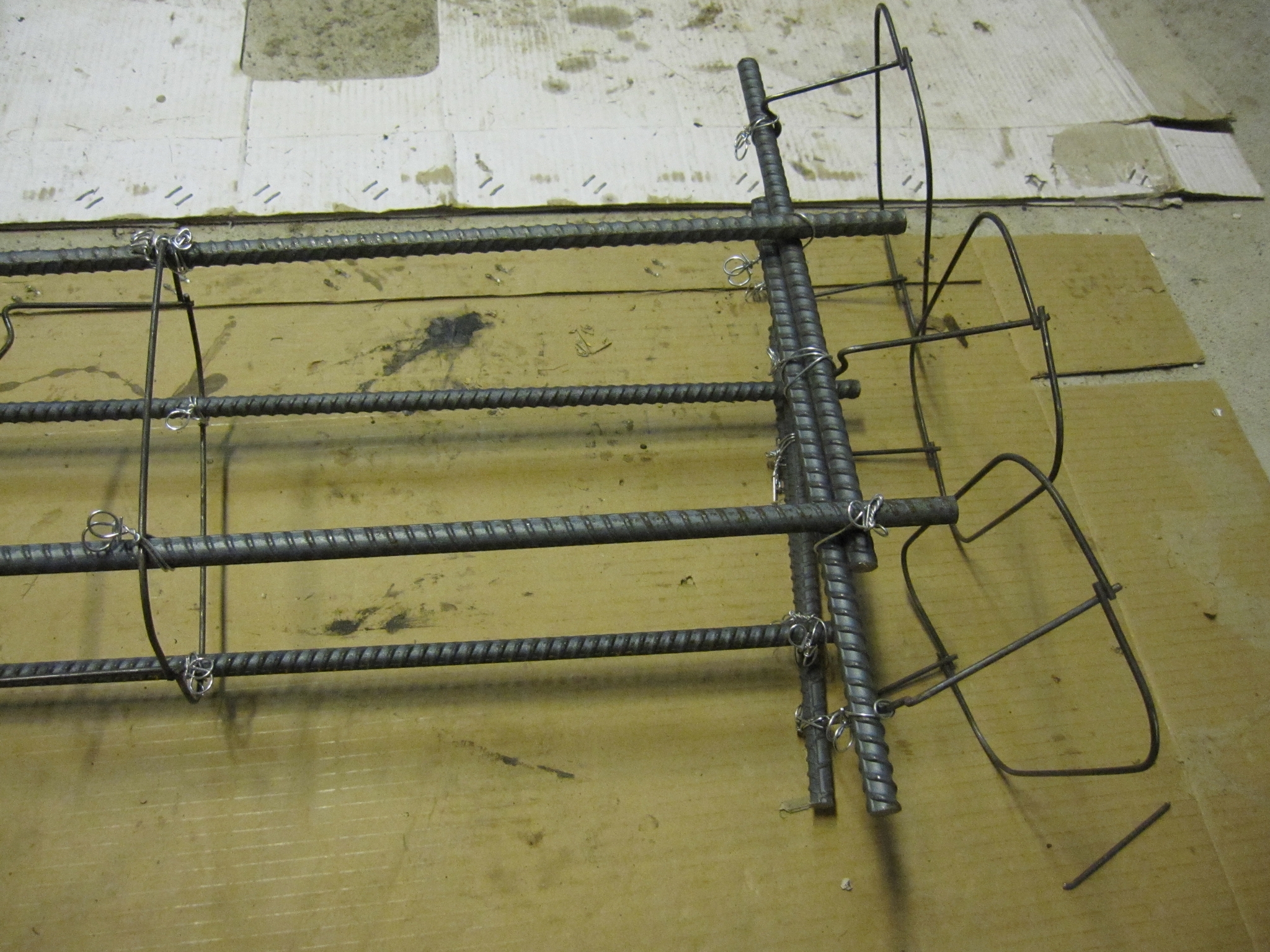 7 Rebar at footing (all of rebar should be kept in the concrete hence the wiring to keep the horizontal rebar (right) up in the air which will be be surrounded by concrete later. |
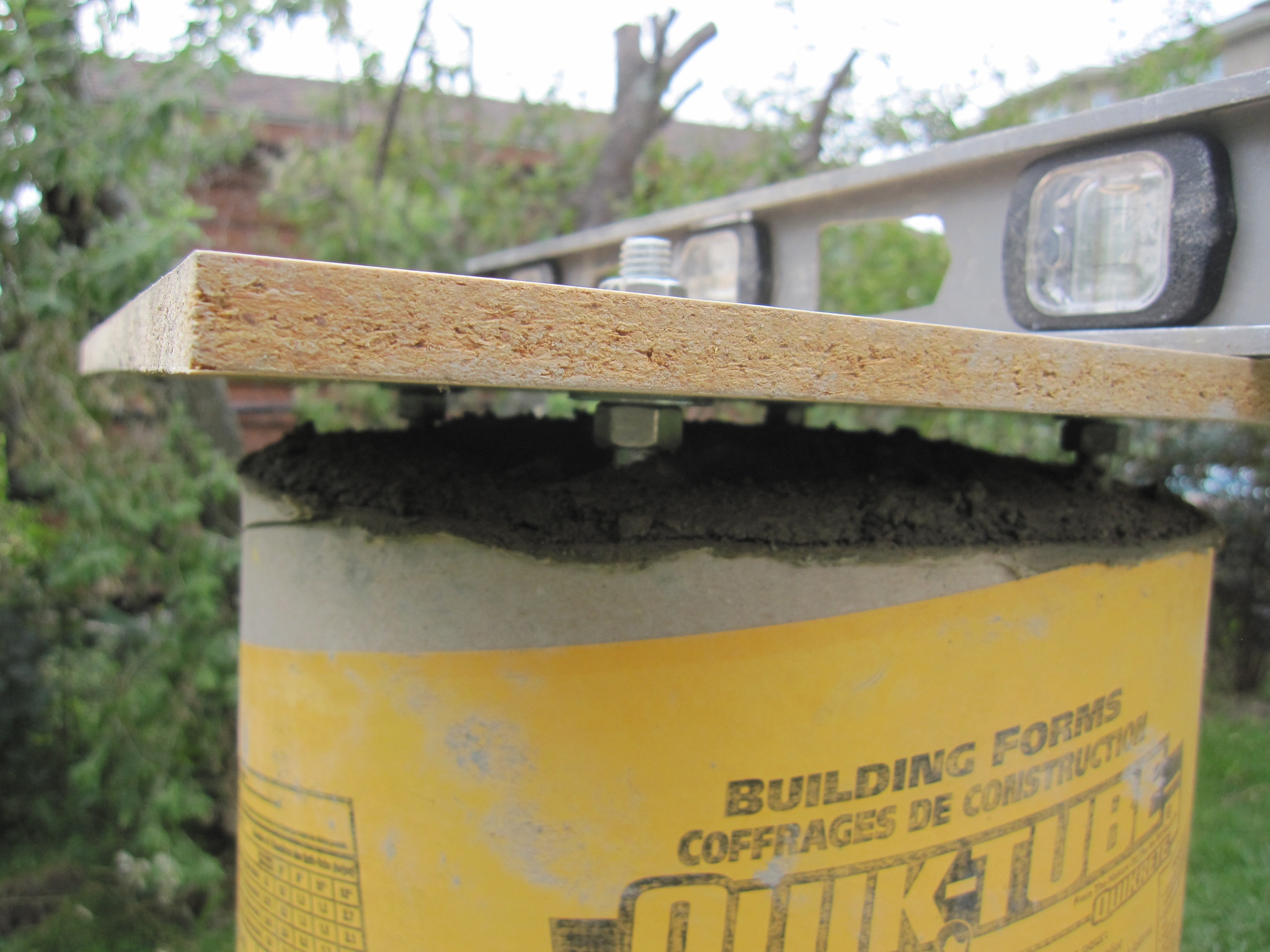
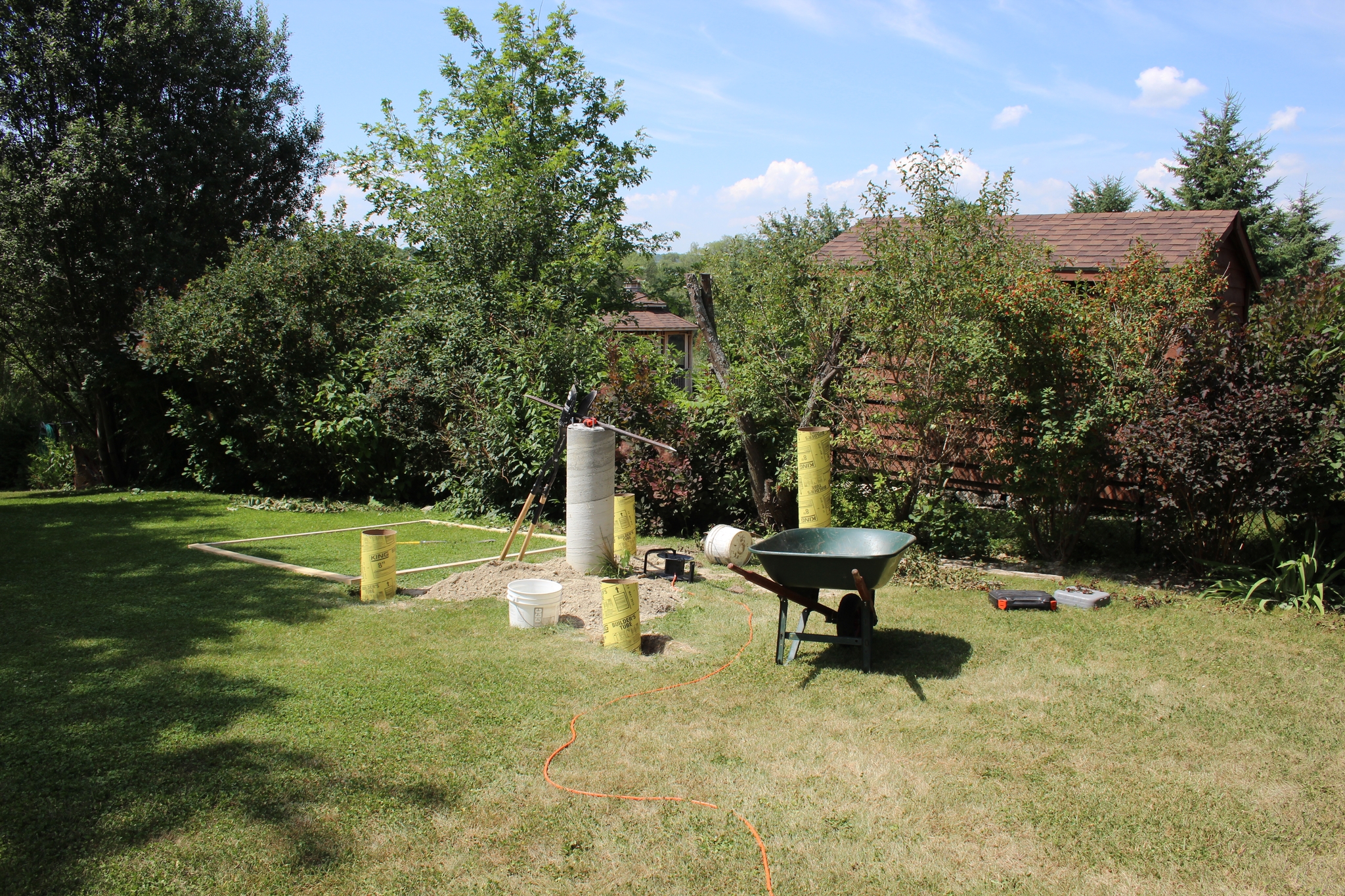
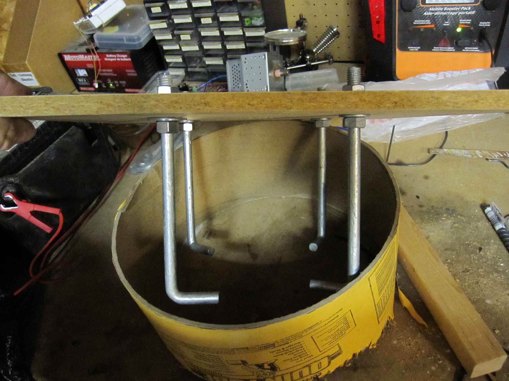 8 Temporary template to space the anchor bolts that will later hold an aluminum template that will hold the mount. |
 9 |
 10 |
 11 |
 12 |
 13 End is in sight... |
 14 |
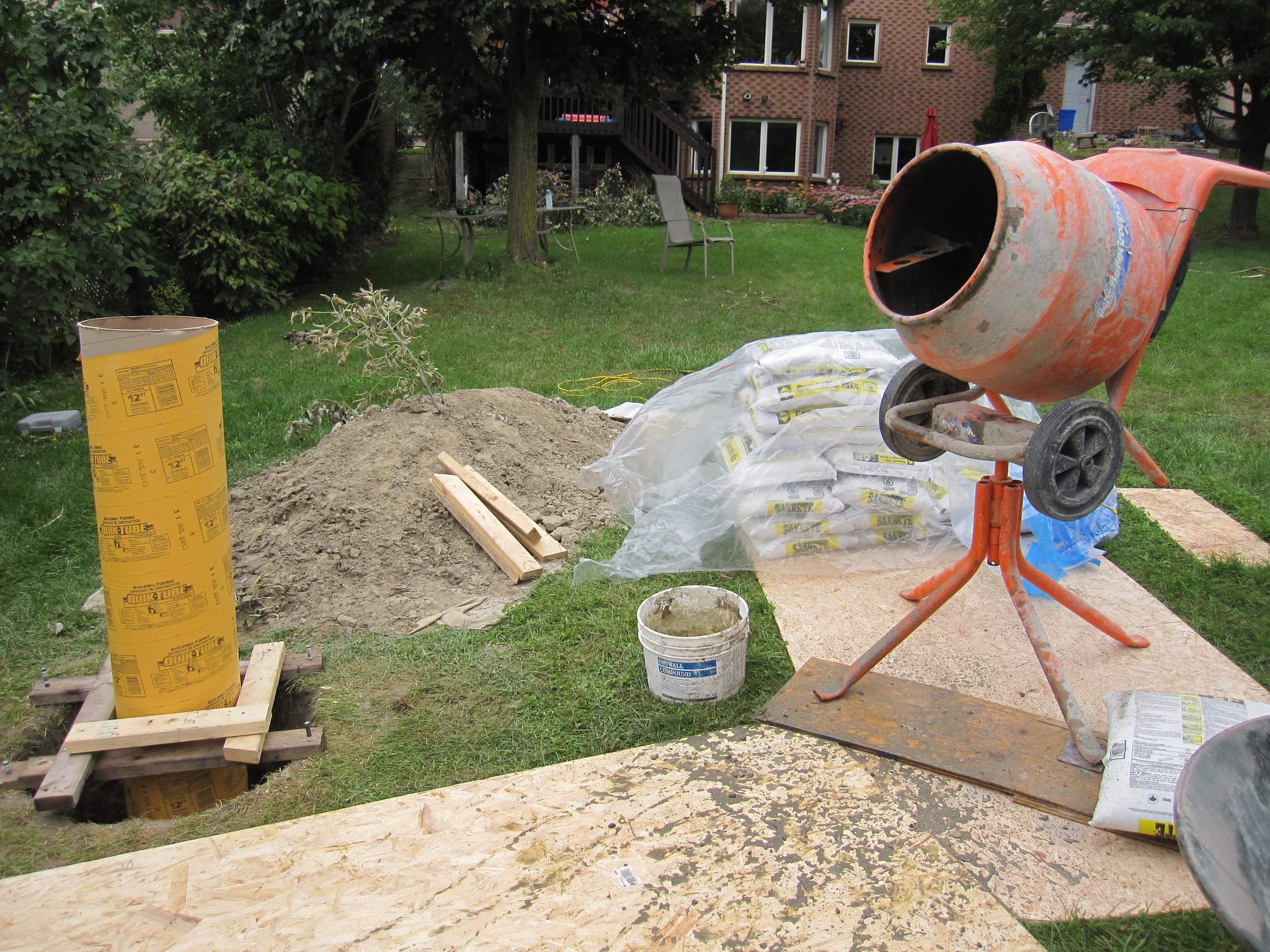
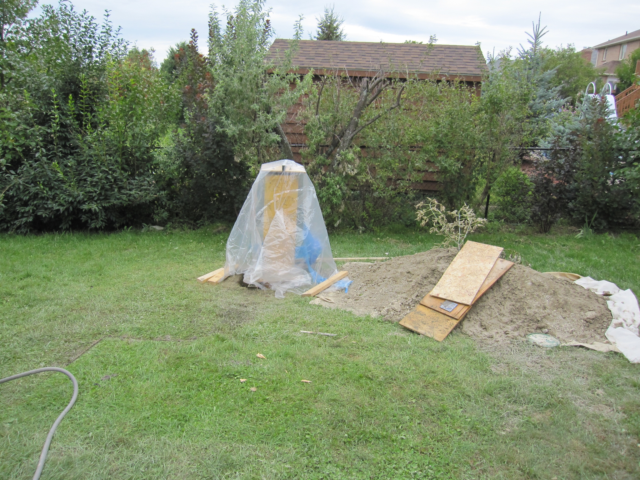 15 Several days and 19 bags (or 570 kg; 1266 lbs) of concrete later... job is done. End of 2014 season. |
 16 Start of construction in July 2015. More than 30C and digging in the rock hard clay again. |
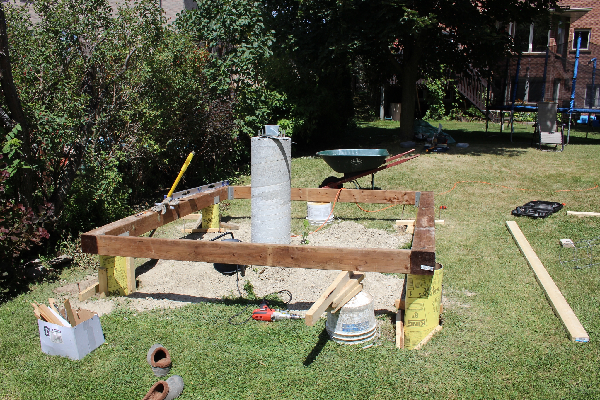 17 It appears to be square though footings are off but there is no way in hell that I am digging more to make it pretty - the adjustable features in the design will have to compensate (and they did). |
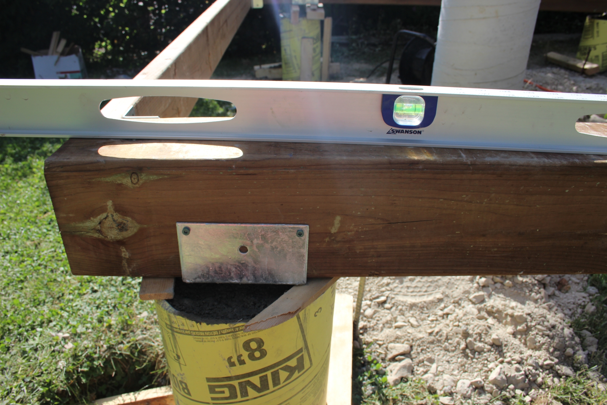 18 One of many miracles: it is very close to level (after concrete has mostly set)! |
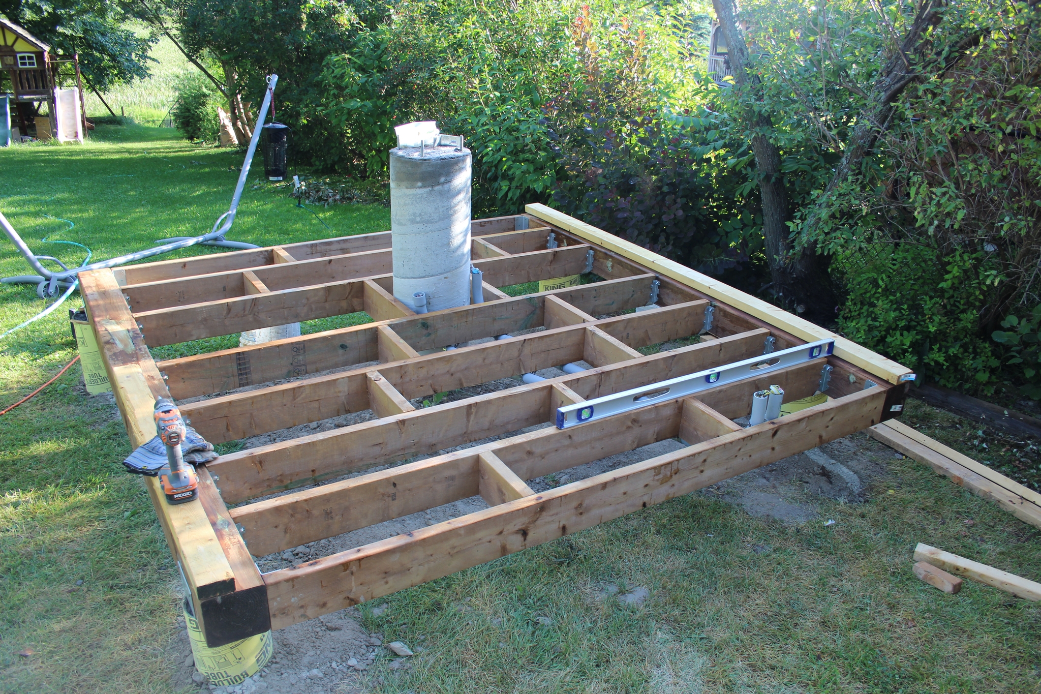 19 The deck and internal wiring conduits. It is square and level and it will be a solid foundation for a straight structure. |
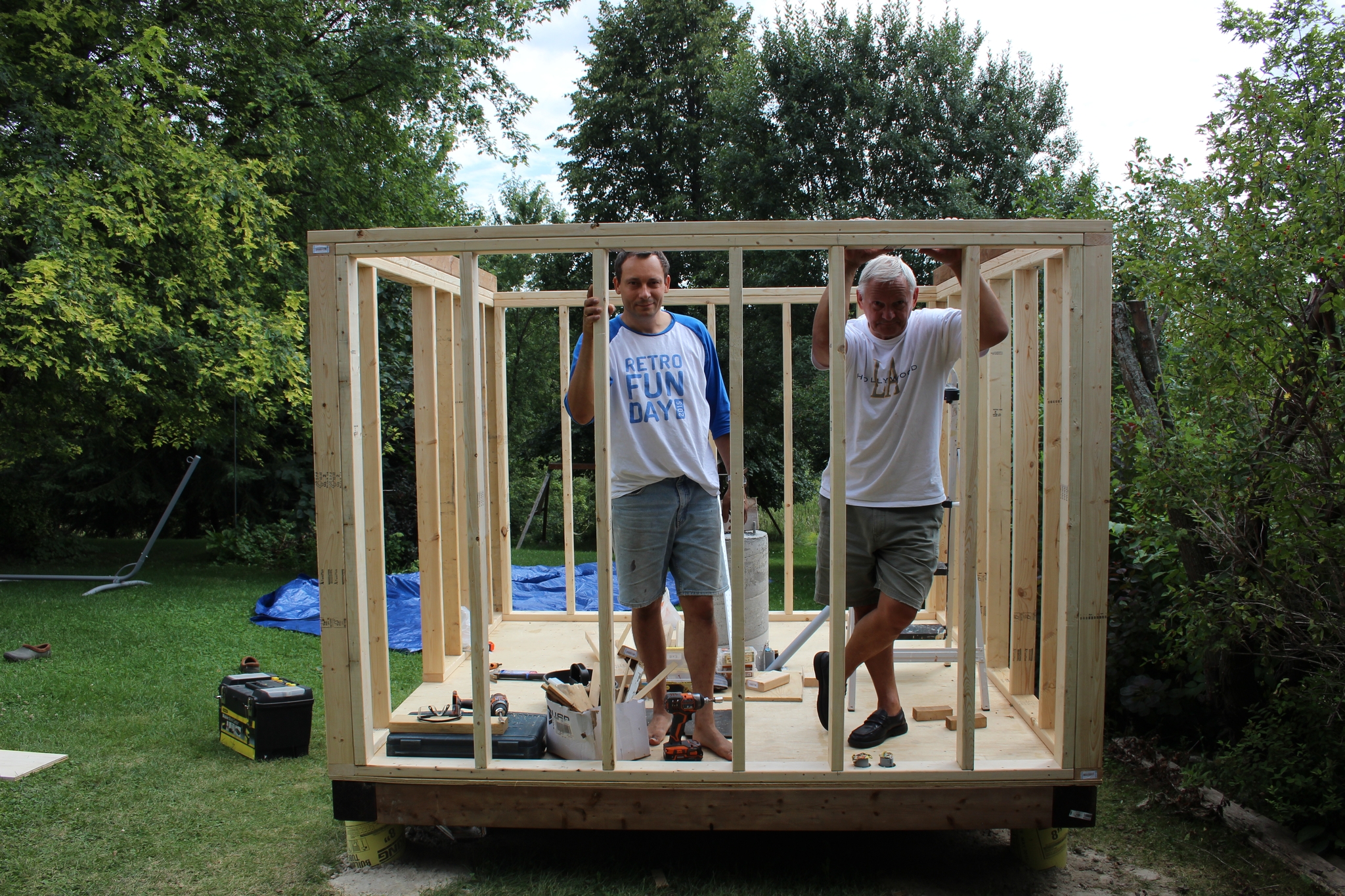 20 After all this, the thing is square (well it is off by 0.25")!! All the measuring and re-measuring paid off. Father came to help and mother kept us fed. |
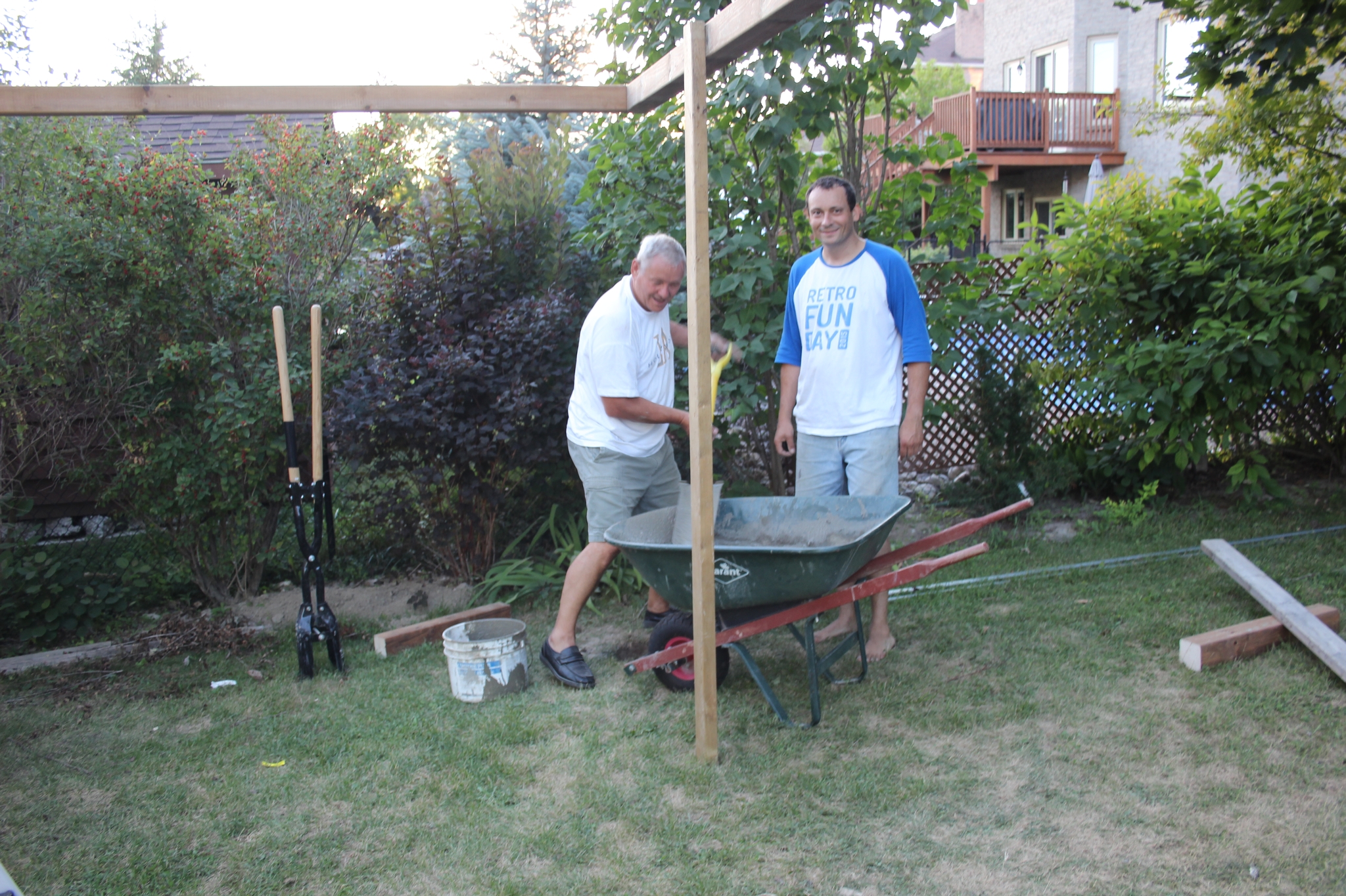 21 Pouring footing for the roller support. |
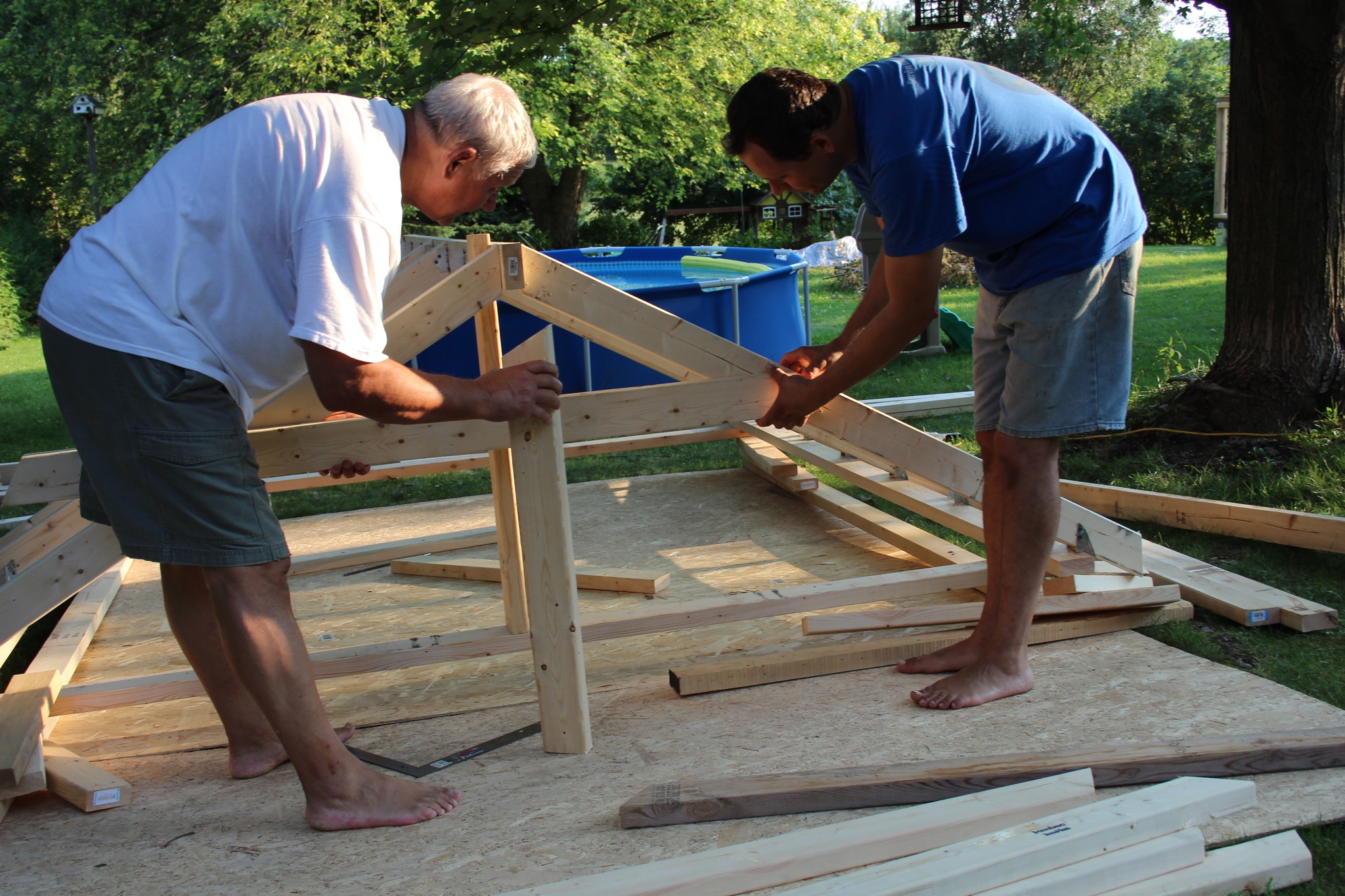 22 The roof proved to be the most challenging to get it right. Father was invaluble for this exercise. |
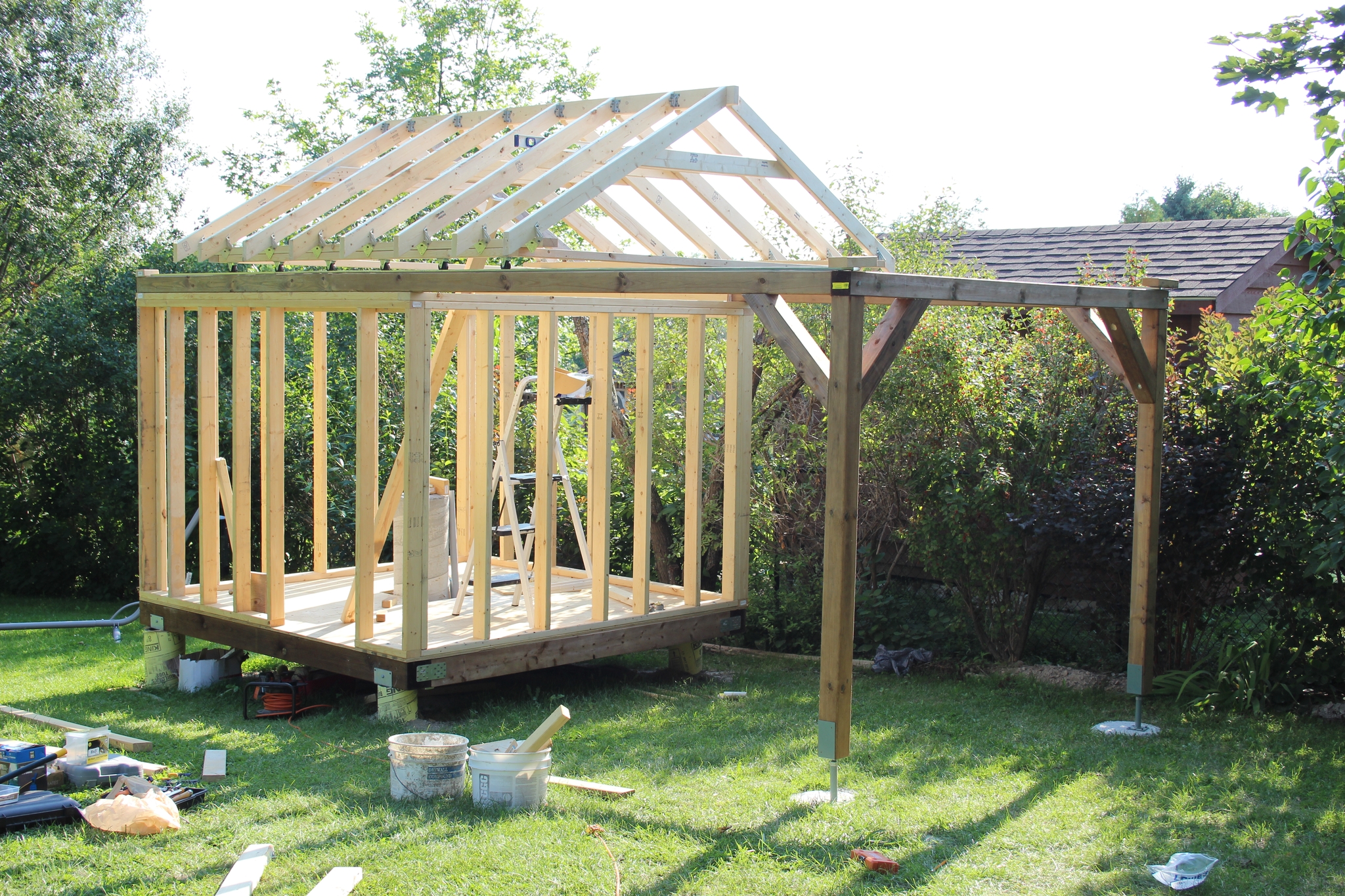
 23 Created the minimum possible before putting it up on its place. |
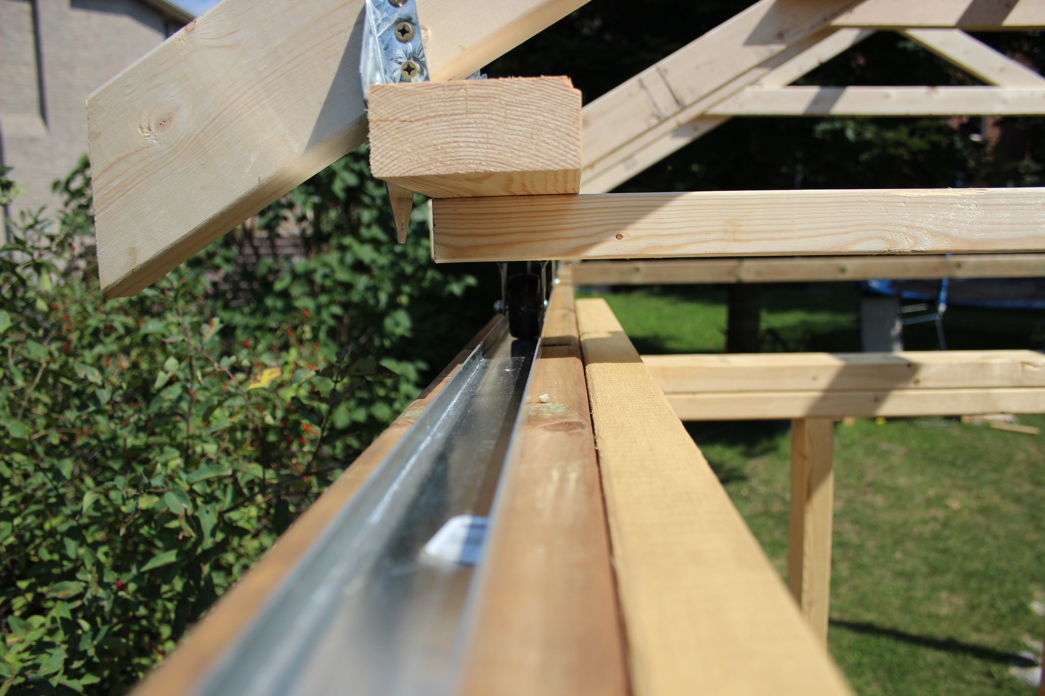 24 The rollers.. |
 25 Seemed like it was almost done... this is just half way... |
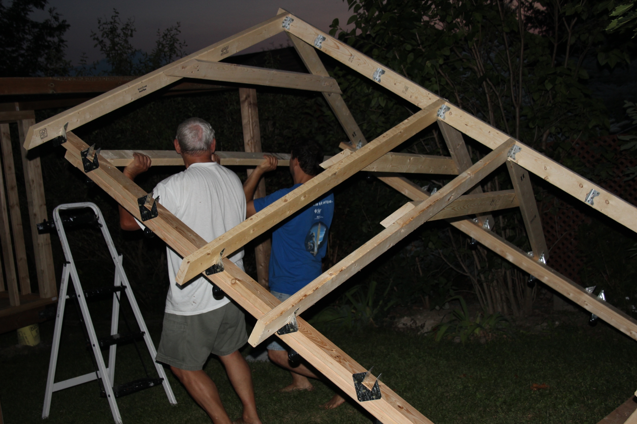
 26 another weekend... |
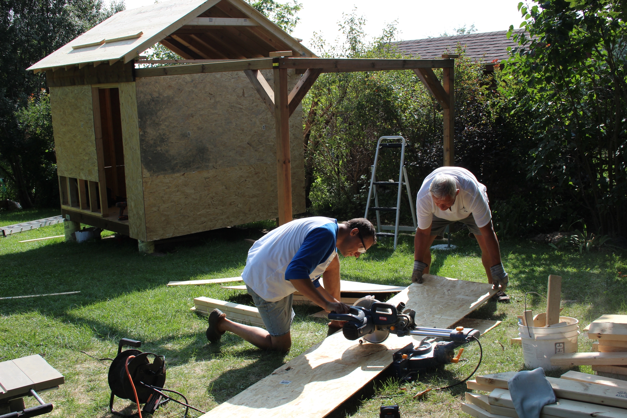
 27 Finally shingles - no more rain damage. |
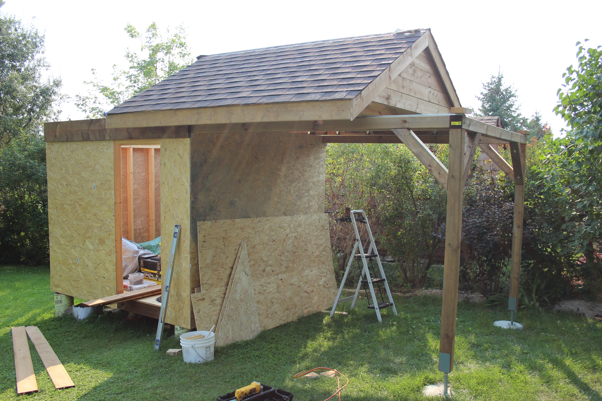
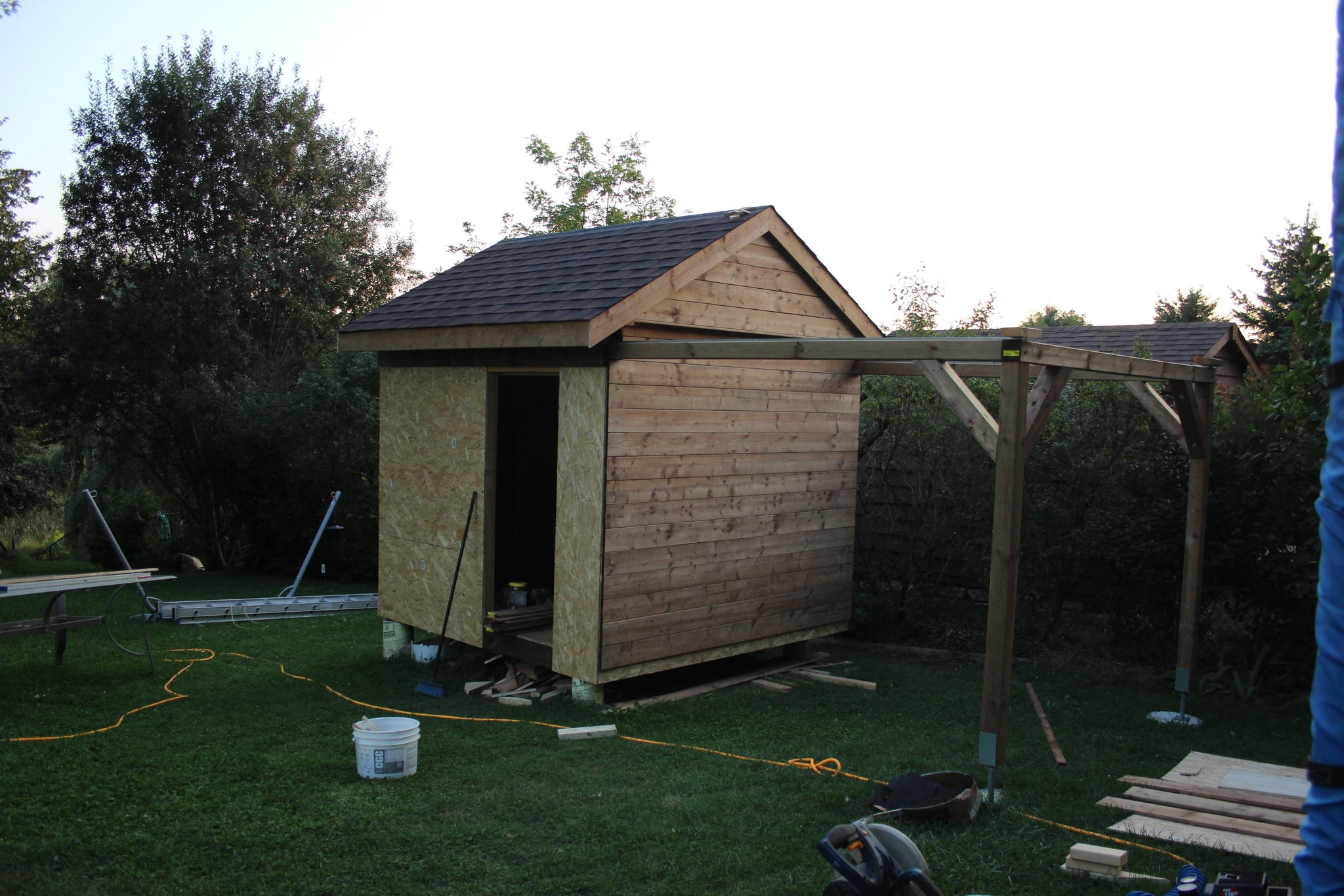 28 It is starting to look like a decent shed... |
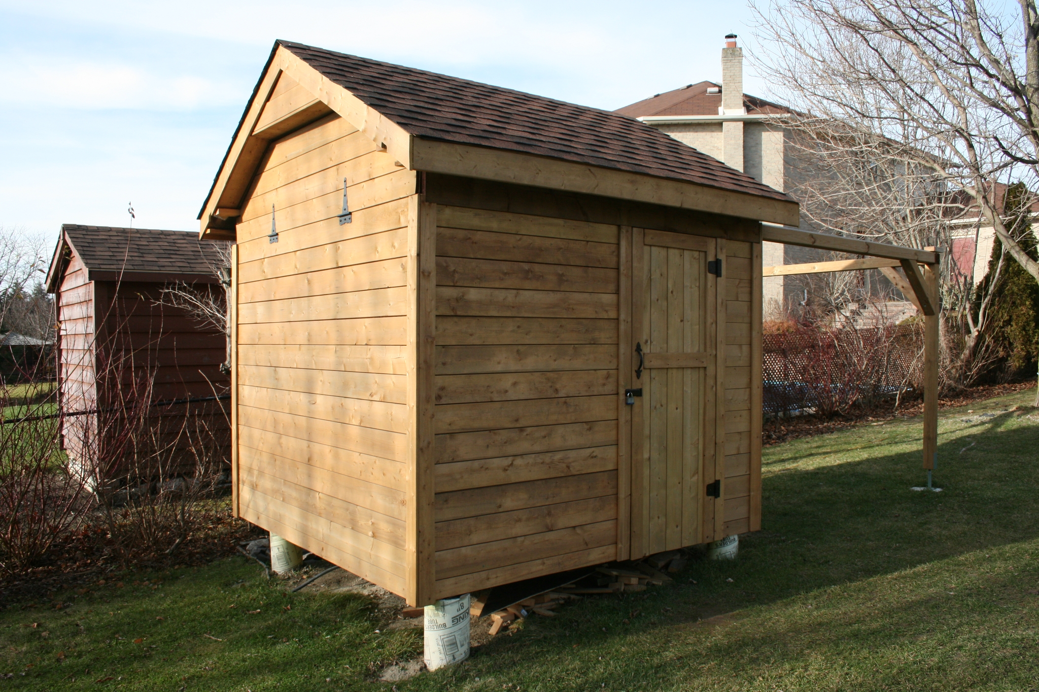
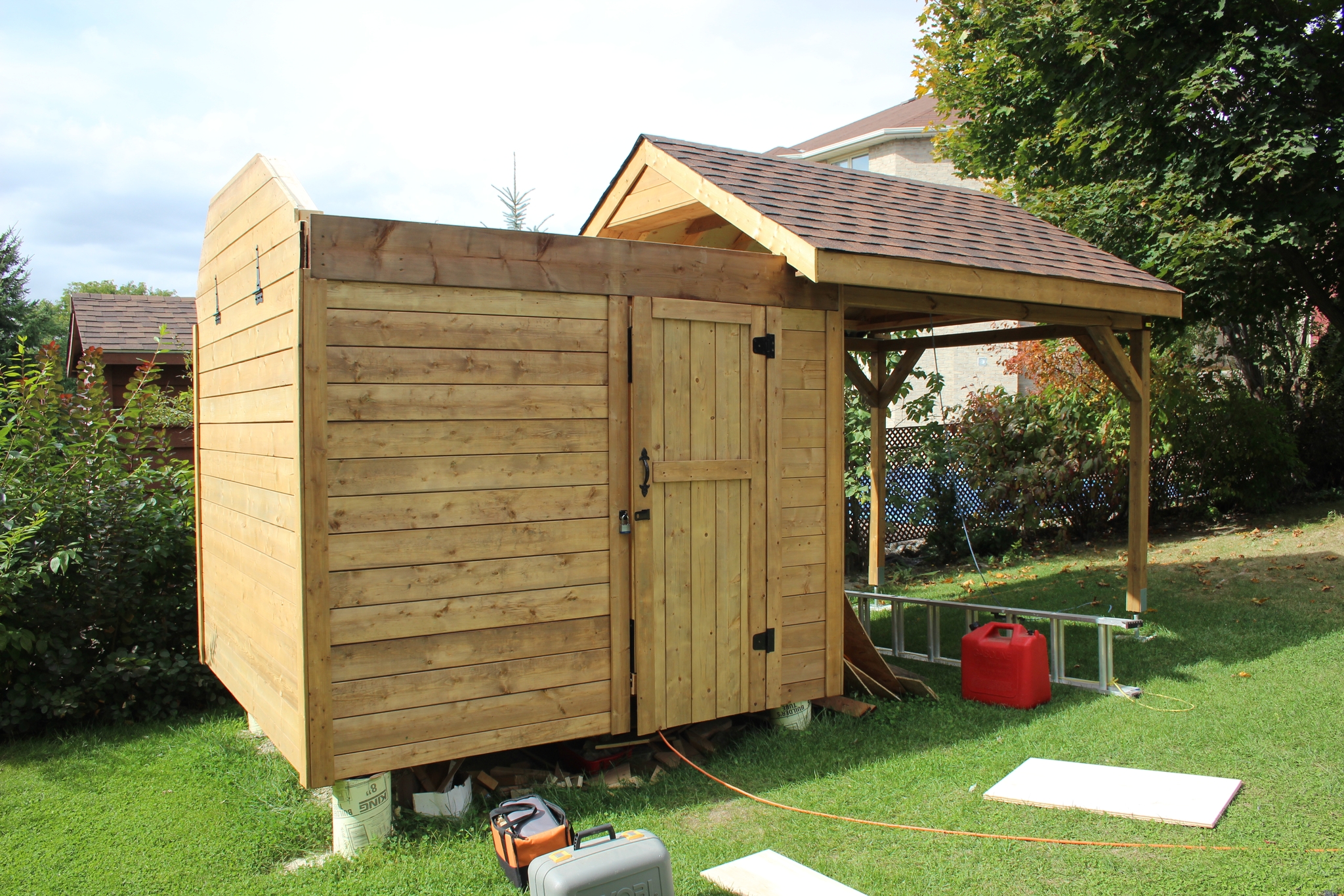 29 Pretty much done the outside. |
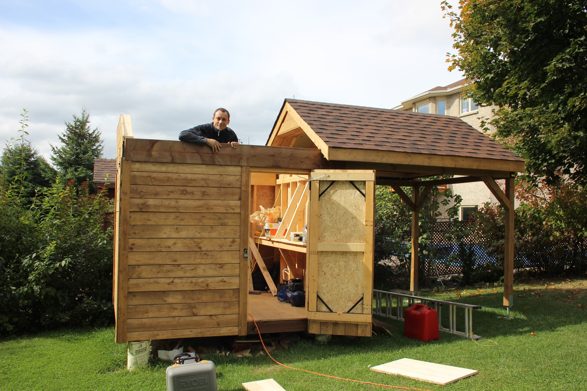 30 |
 31 The observatory plugs into a regular socket via an extension coord :) The wiring inside is just like a normal house with wall sockets and will mostly be 12V powered. |
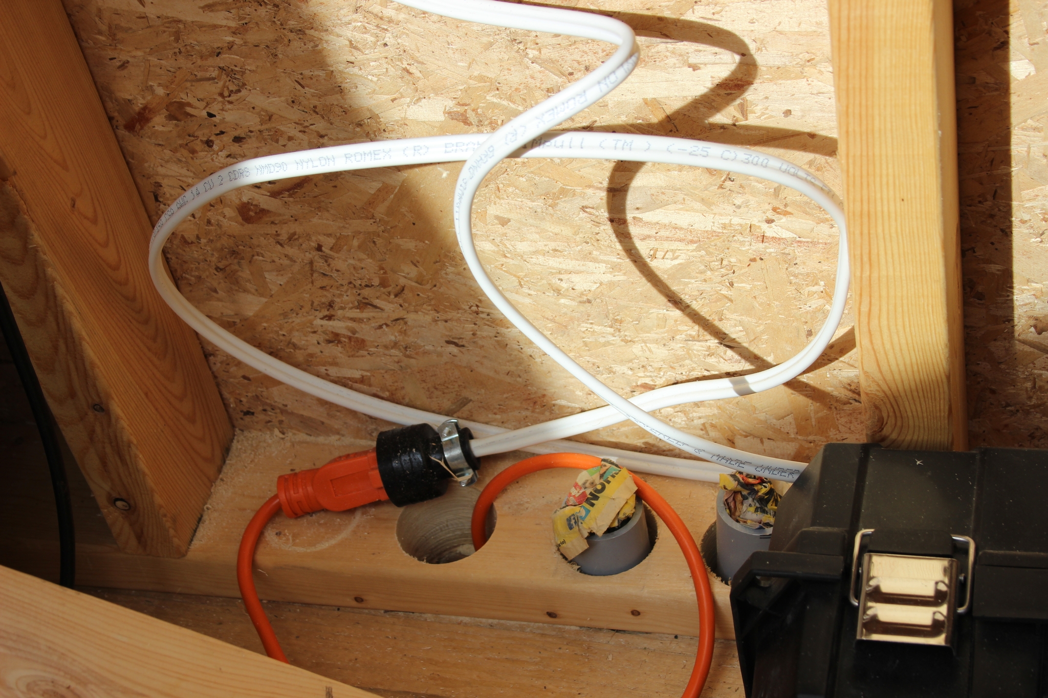
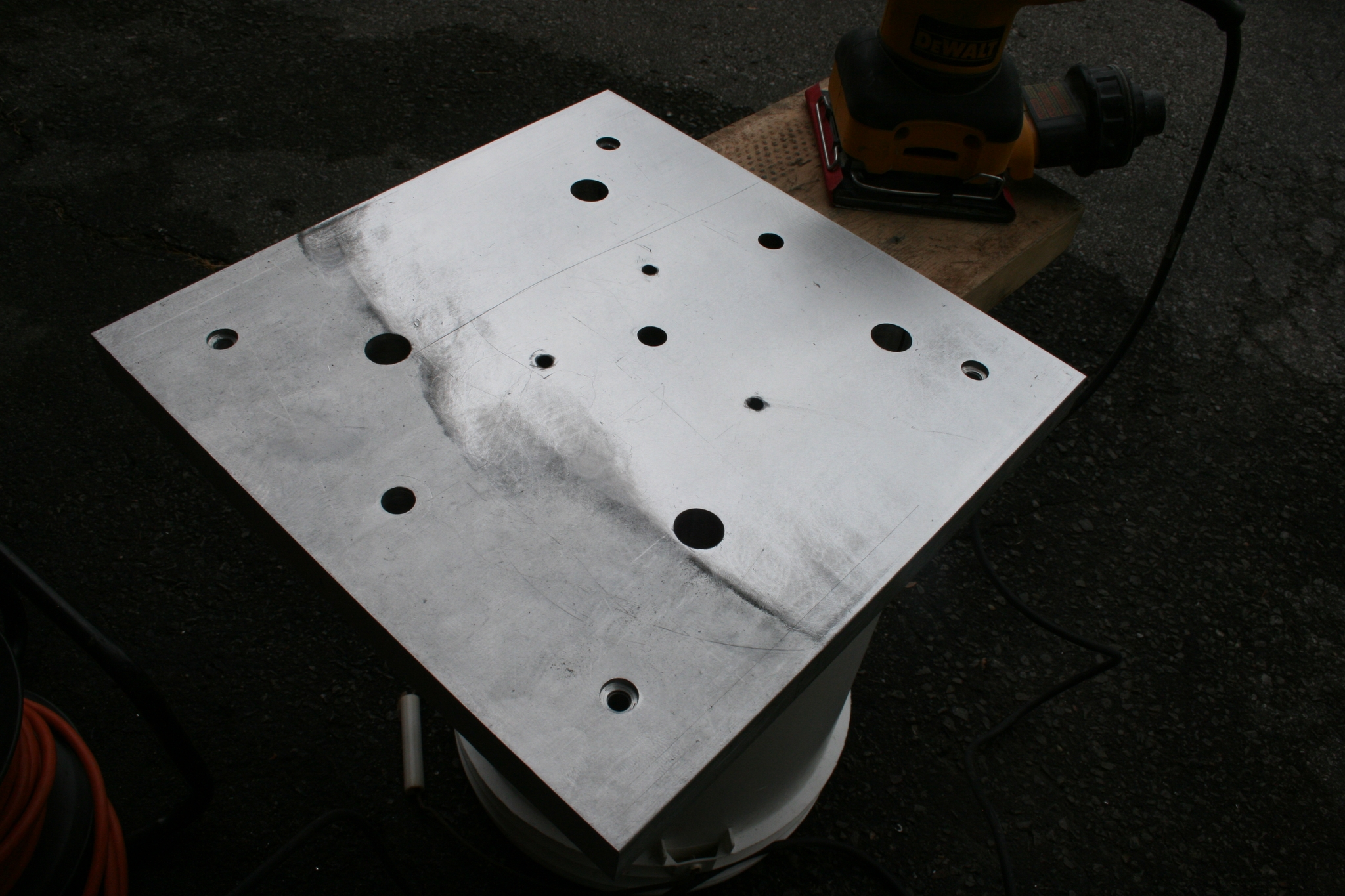
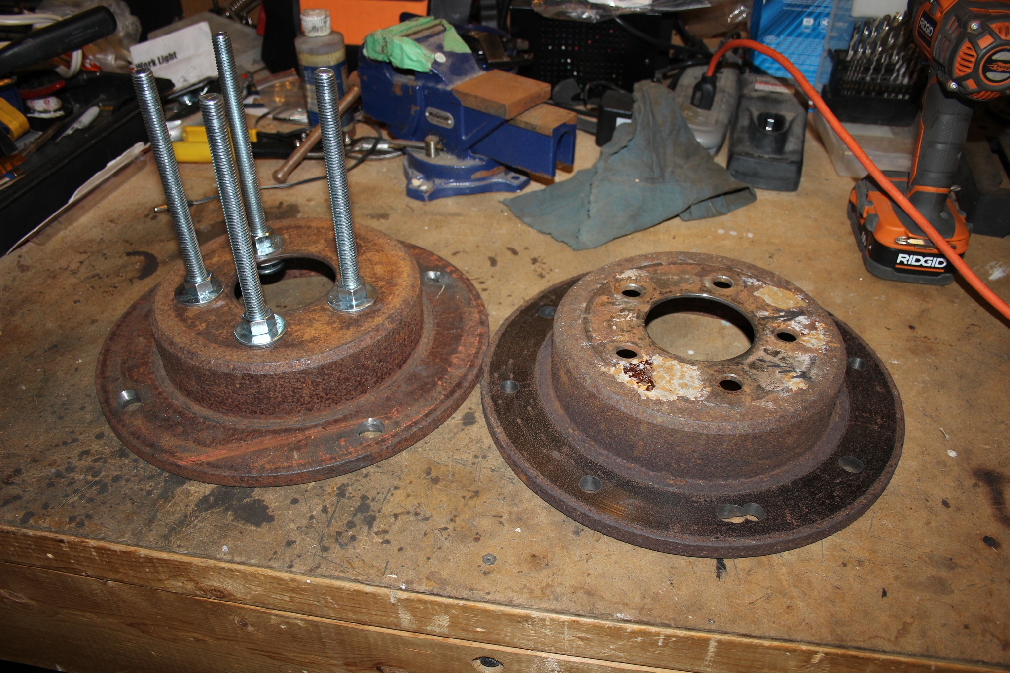 32 Before/raw picture of the materials used for the mount head. |
 33 old L beam to be used to hold the factory made mount's mount head |
 34 I love using the grinders - they make a lot of sparks and they work! Cuts through steel and concrete beautifully. |
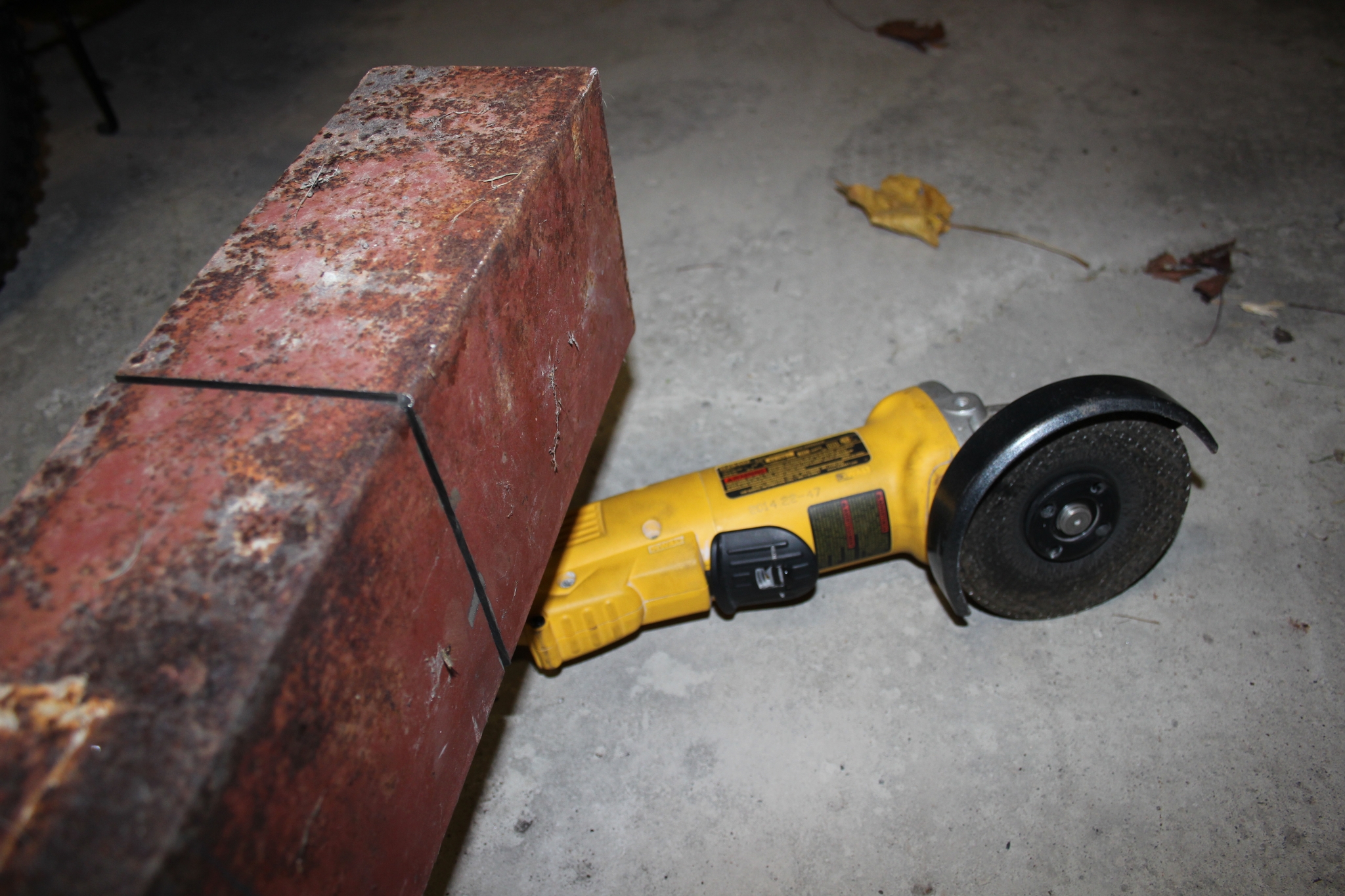
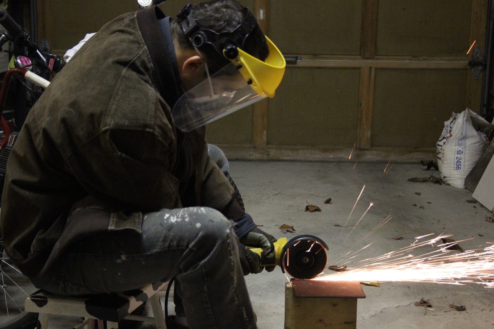
 35 Proof of concept that the two rotors will space sufficiently for the rest of the mount. Definitely not the pretiest and probably not the most clean and stable solution but for now it will have to do. |
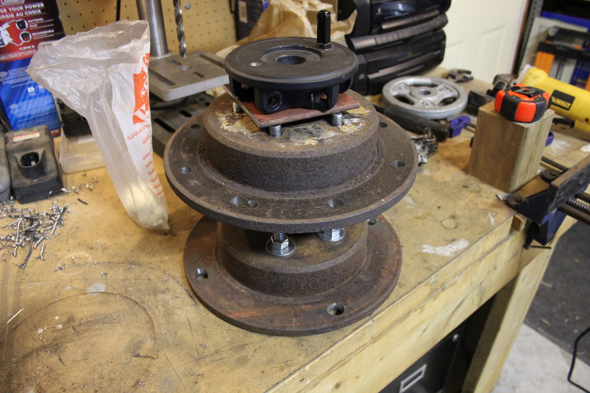
 36 Up side that it will look better than the rusted scrap metal I started with. |
 37 looks ok |
 38 Initial drift alignment yielded perfect round stars; I was checking if the mount is stable and later got drift. So the mount is not as stable as I would like it to be - will have to re-align and see if it holds without touching. Later I'll have to re-build the pier coupling. |
 39 The finished product (at least externally). |
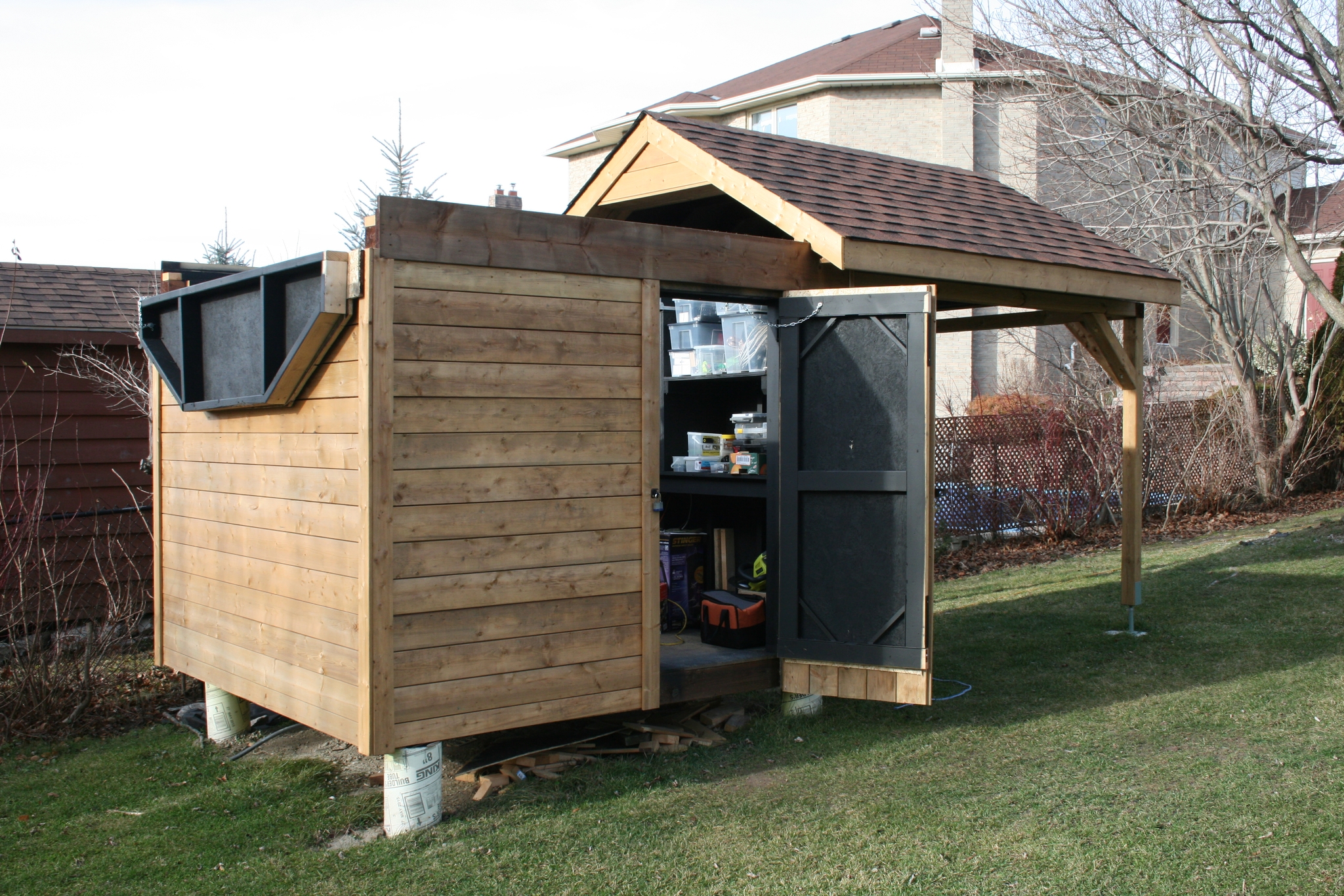
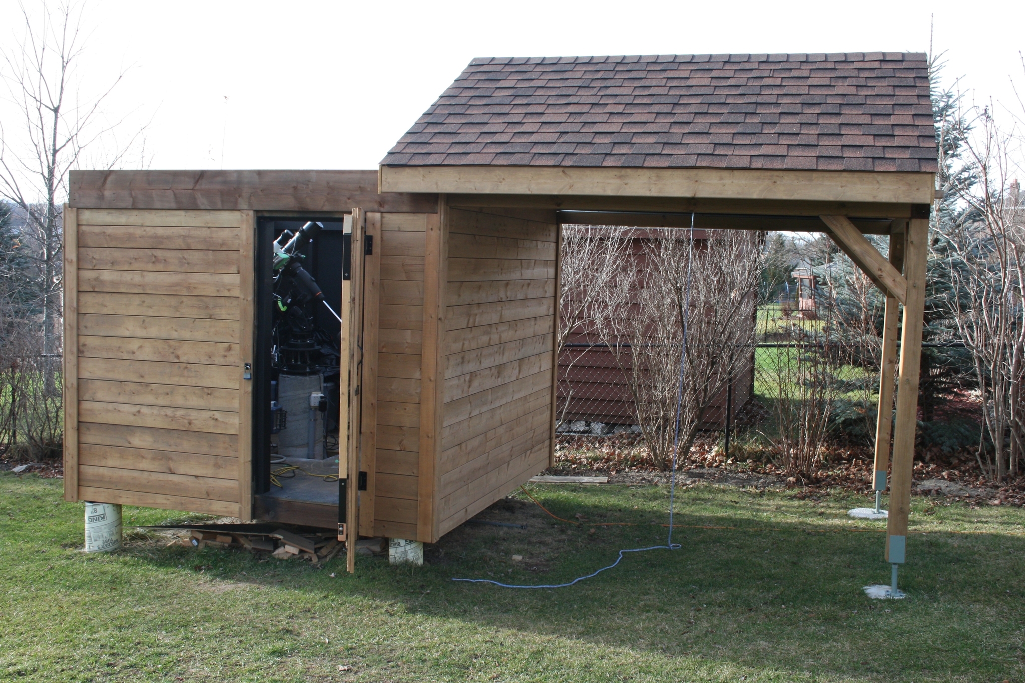 40 The roof opens as planned. |
 41 Part of the side flips open. |
 42 The rail and wheel solution. A bit rough when rolling so closing the roof is a bit painful but it is working well. |
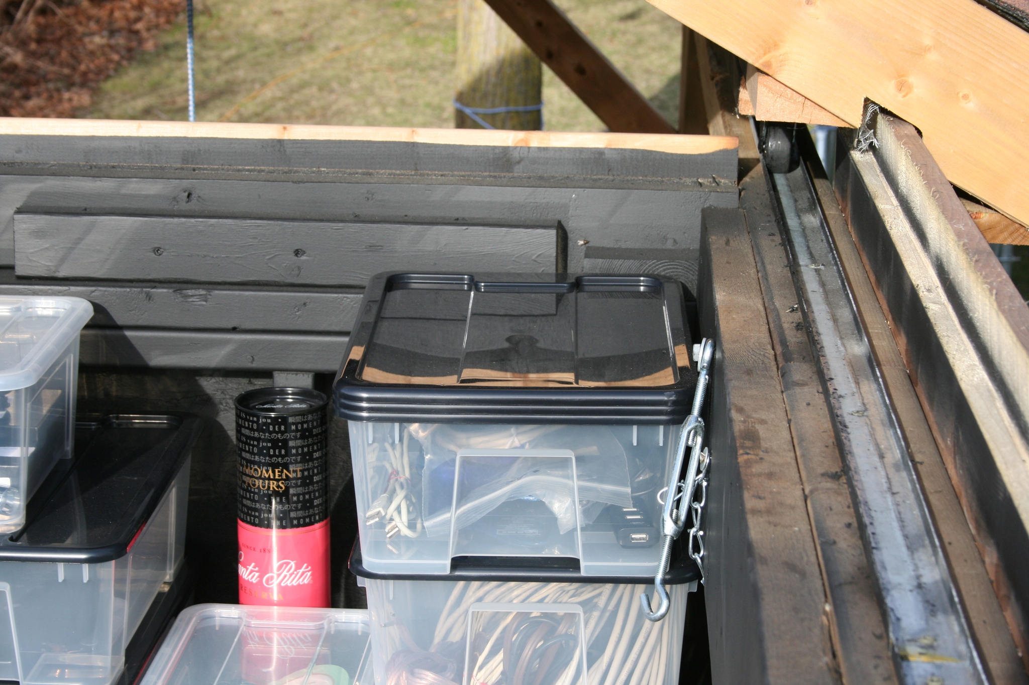
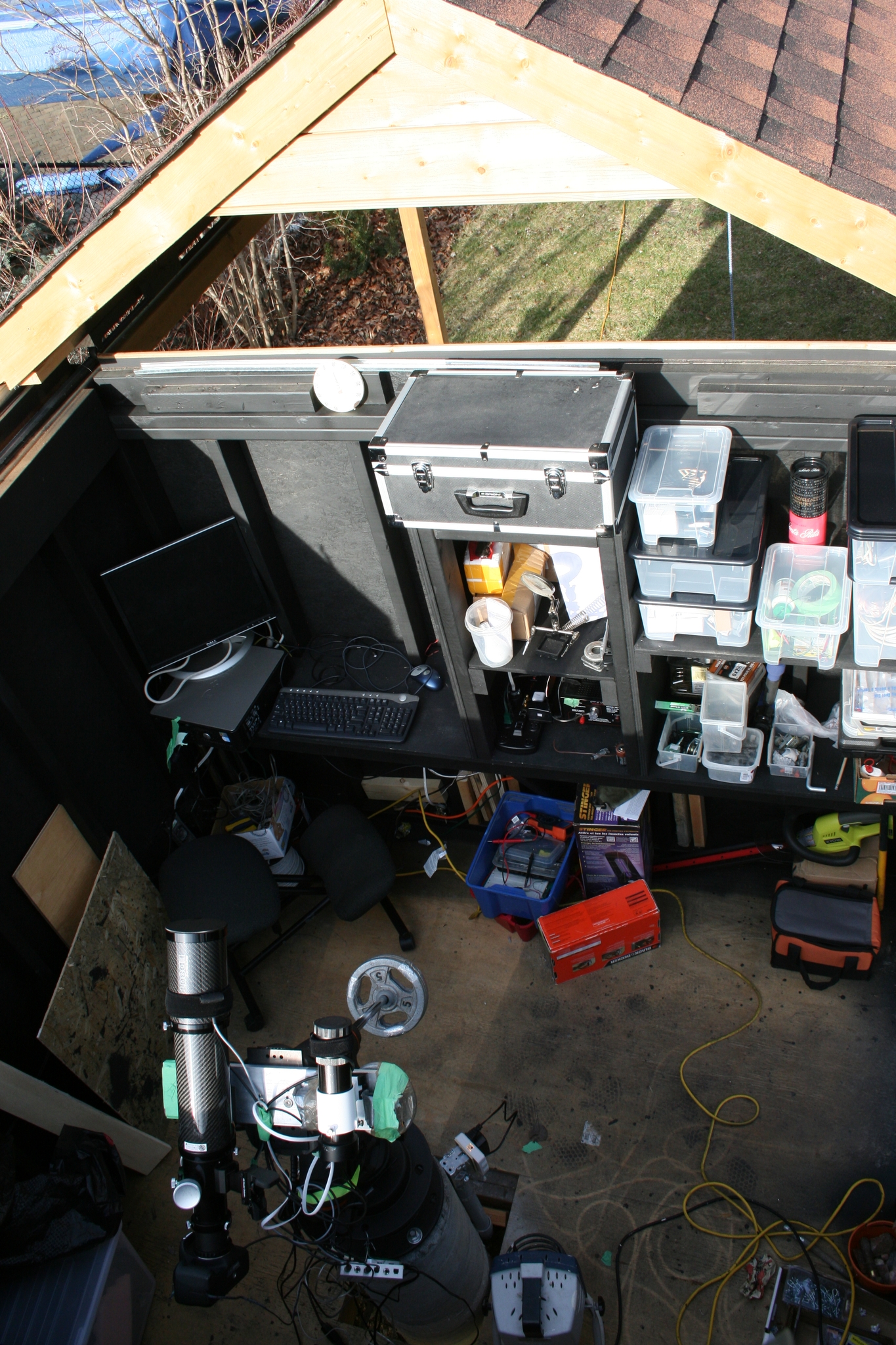 43 Inside still under construction so it is still messy but it is operational. |
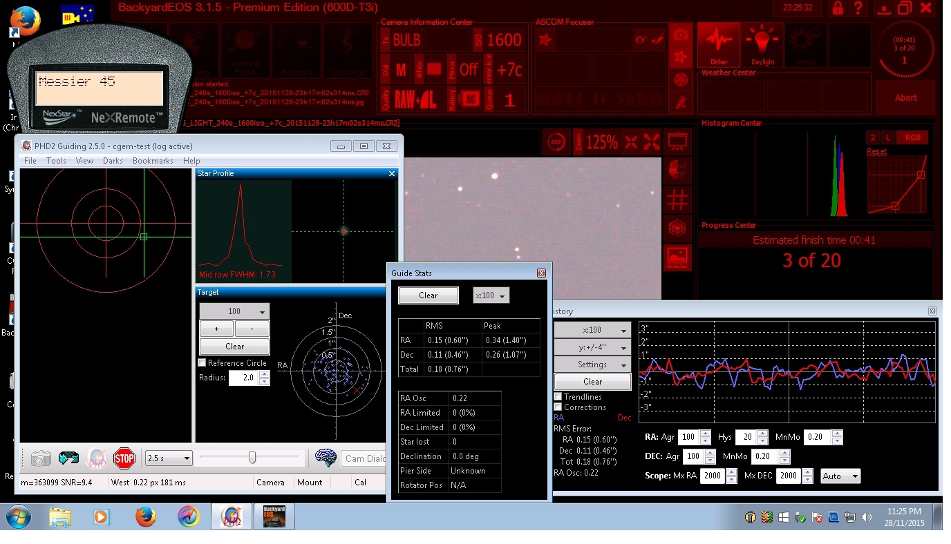 44 Screen capture: Guiding results (a bit rough - need more tweeking - later sessions showed that it is possible). |
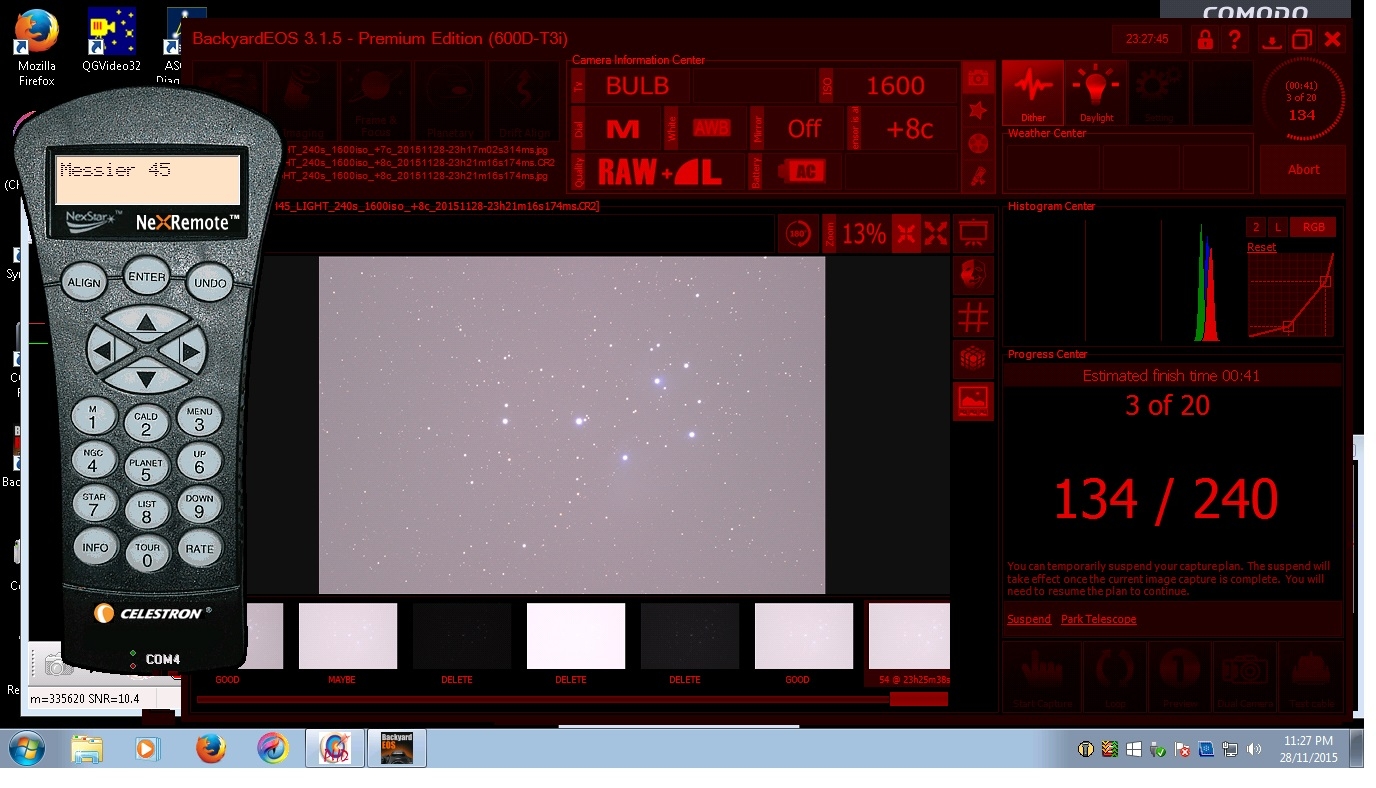 45 Screen capture: image aquisition. |
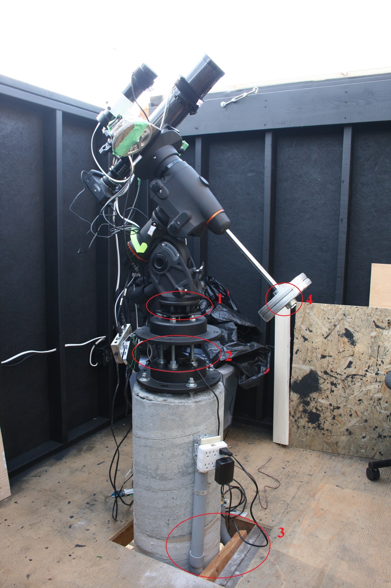 46 Pier adapter mistakes: 1) original tripod adapter - somewhat shameful, most likely reason for losing alignment if the scope shifted when after a meridian flip 2) 'rat cage' approach = tunning fork = vibration amplificator = very bad idea 3) electrical conduit bridges the floor with the pier - not a major source of vibration but with the tunning fork amplification it is bad enough 4) weight shift may be contributing to erratic tracking at times |
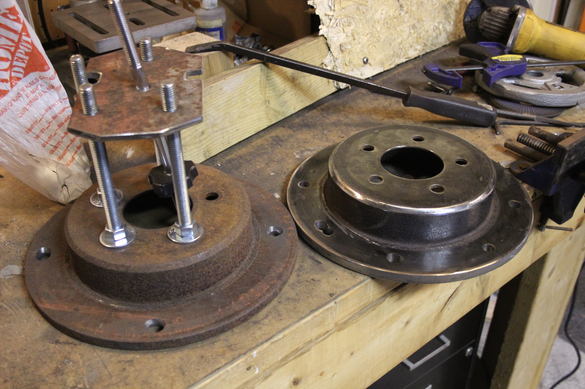
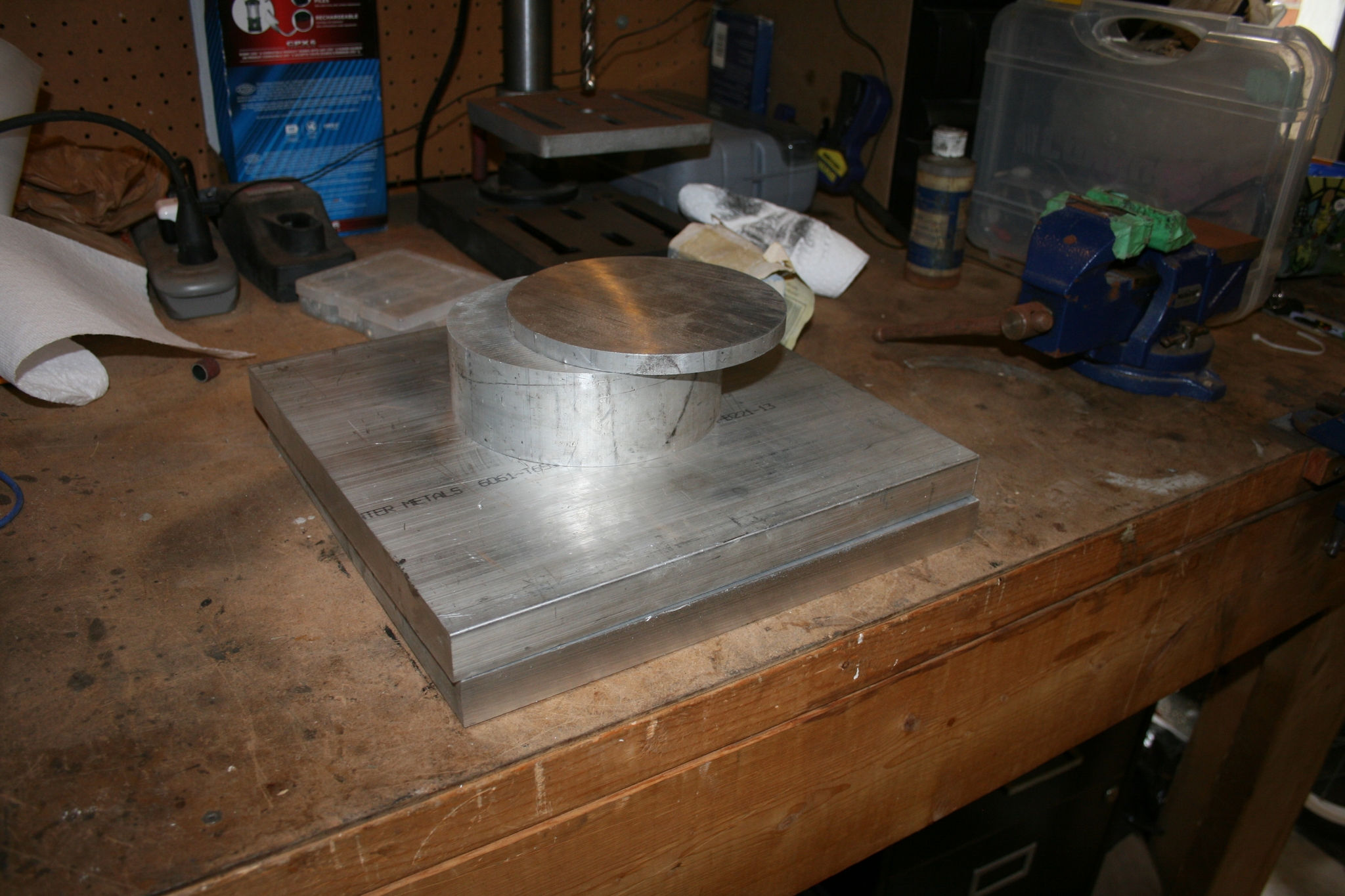 47 The raw materials to redo the pier adapter from scratch. |
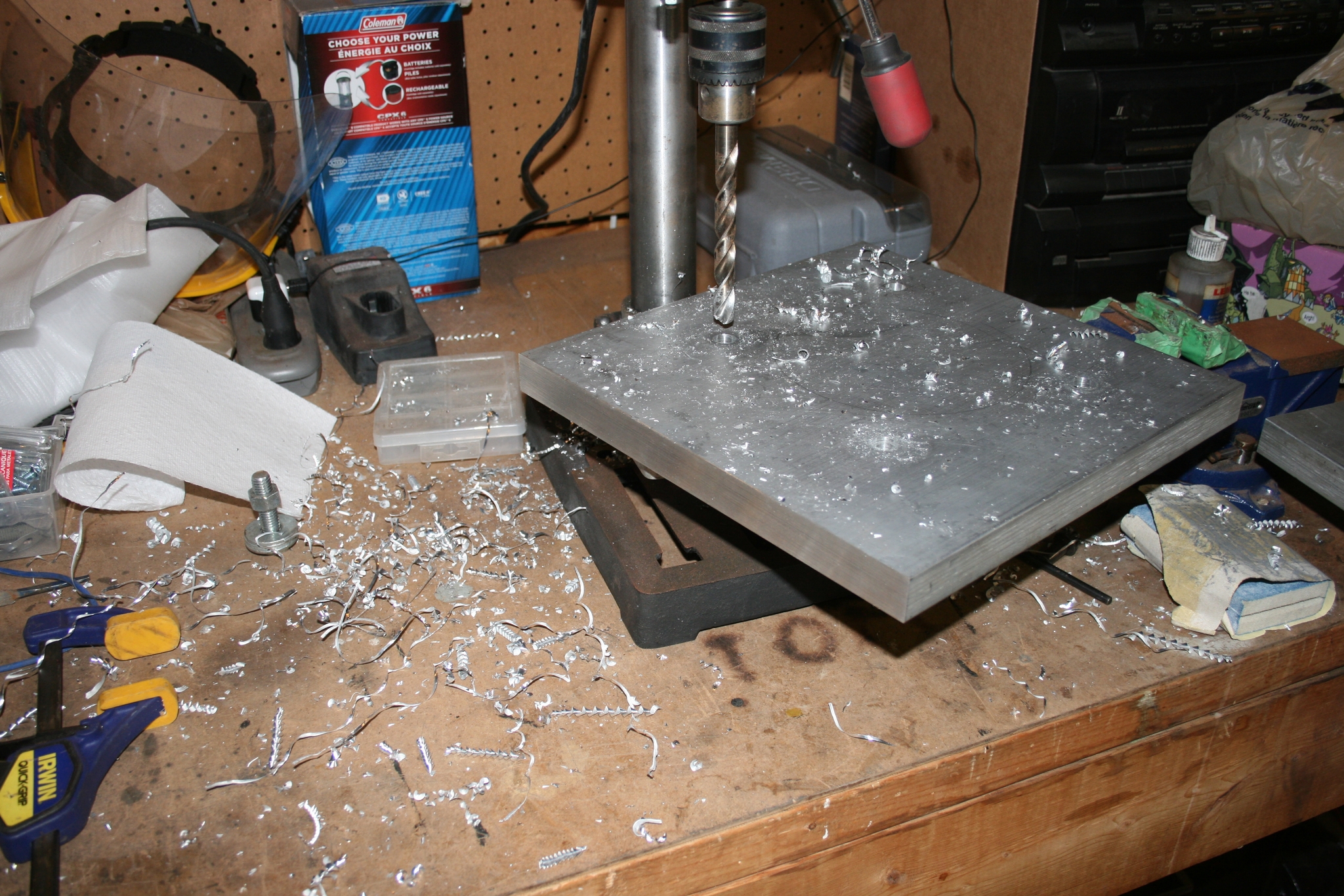 48 Way easier to drill in the soft aluminum vs. steel. |
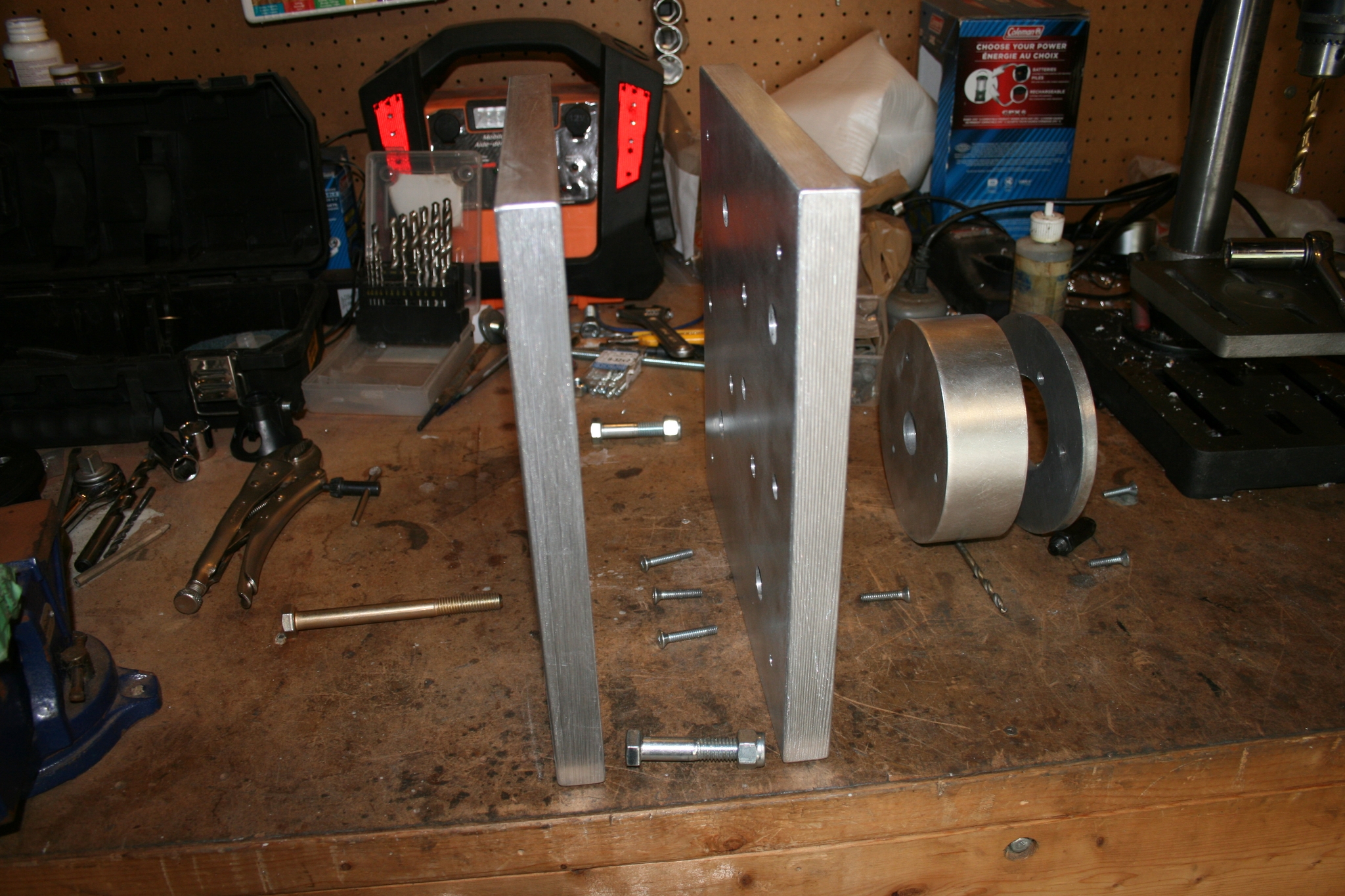
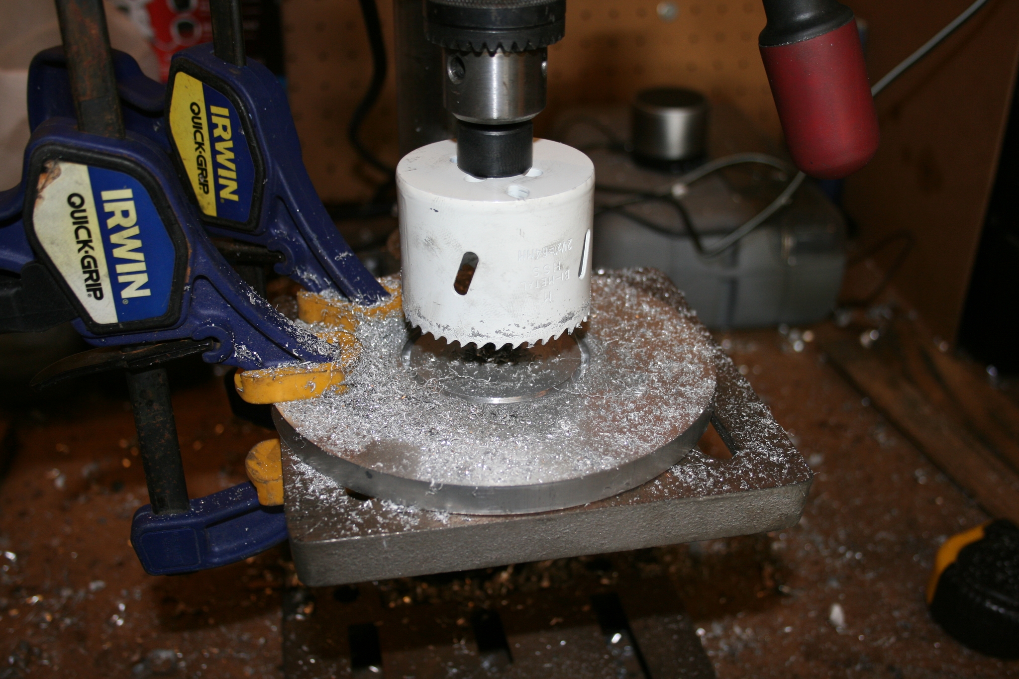 49 First part of the mount adapter (2.5" diameter) |
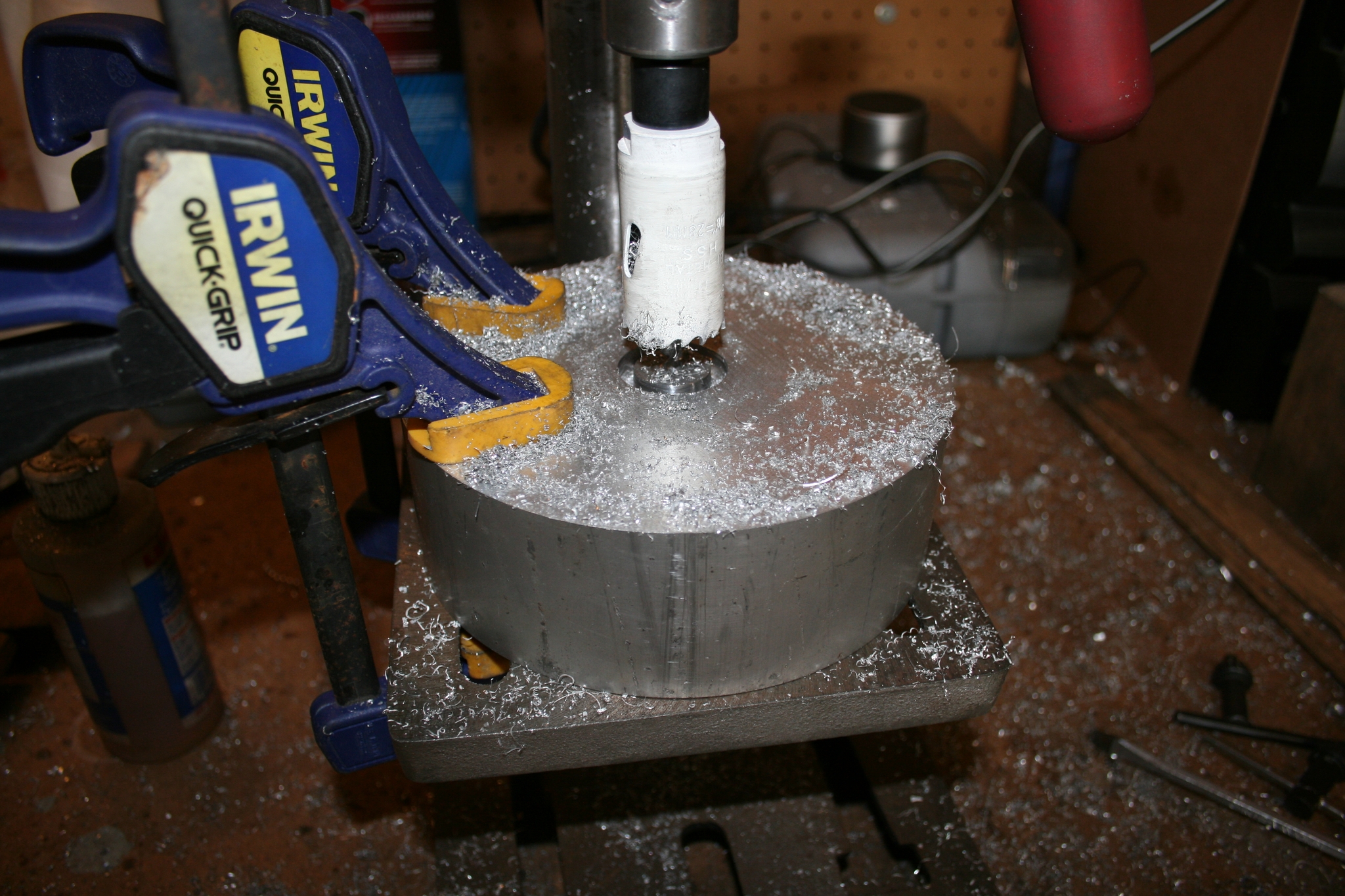 50 Second part of the adapter (1 1/8 " diameter hole in the 2 inch block) |
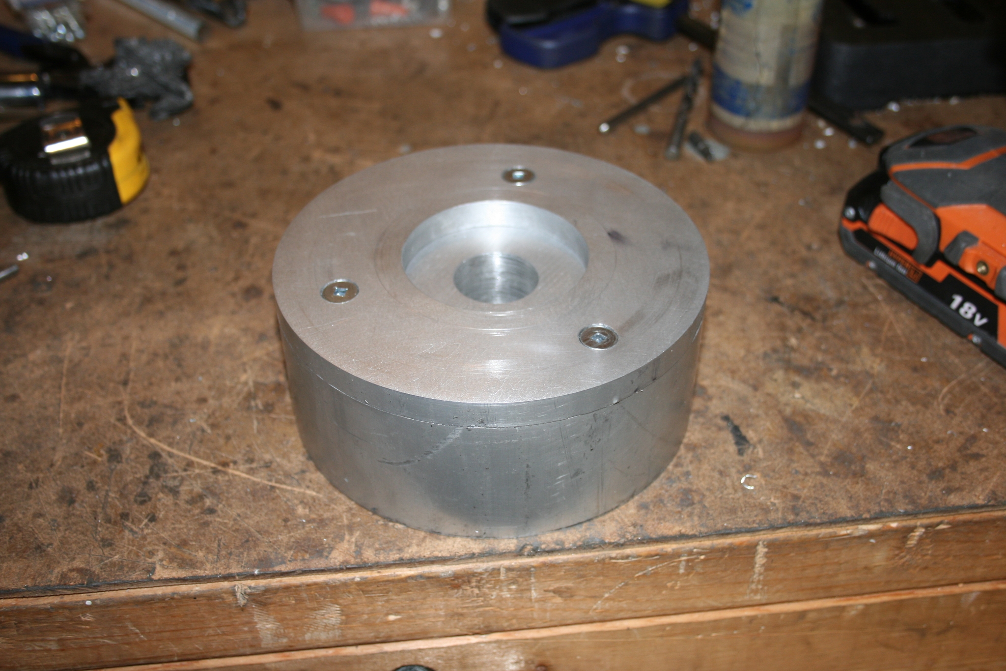 51 The two make an adapter that usually is one solid piece but for the lack of a milling machine, this is another way to achieve the same thing. |
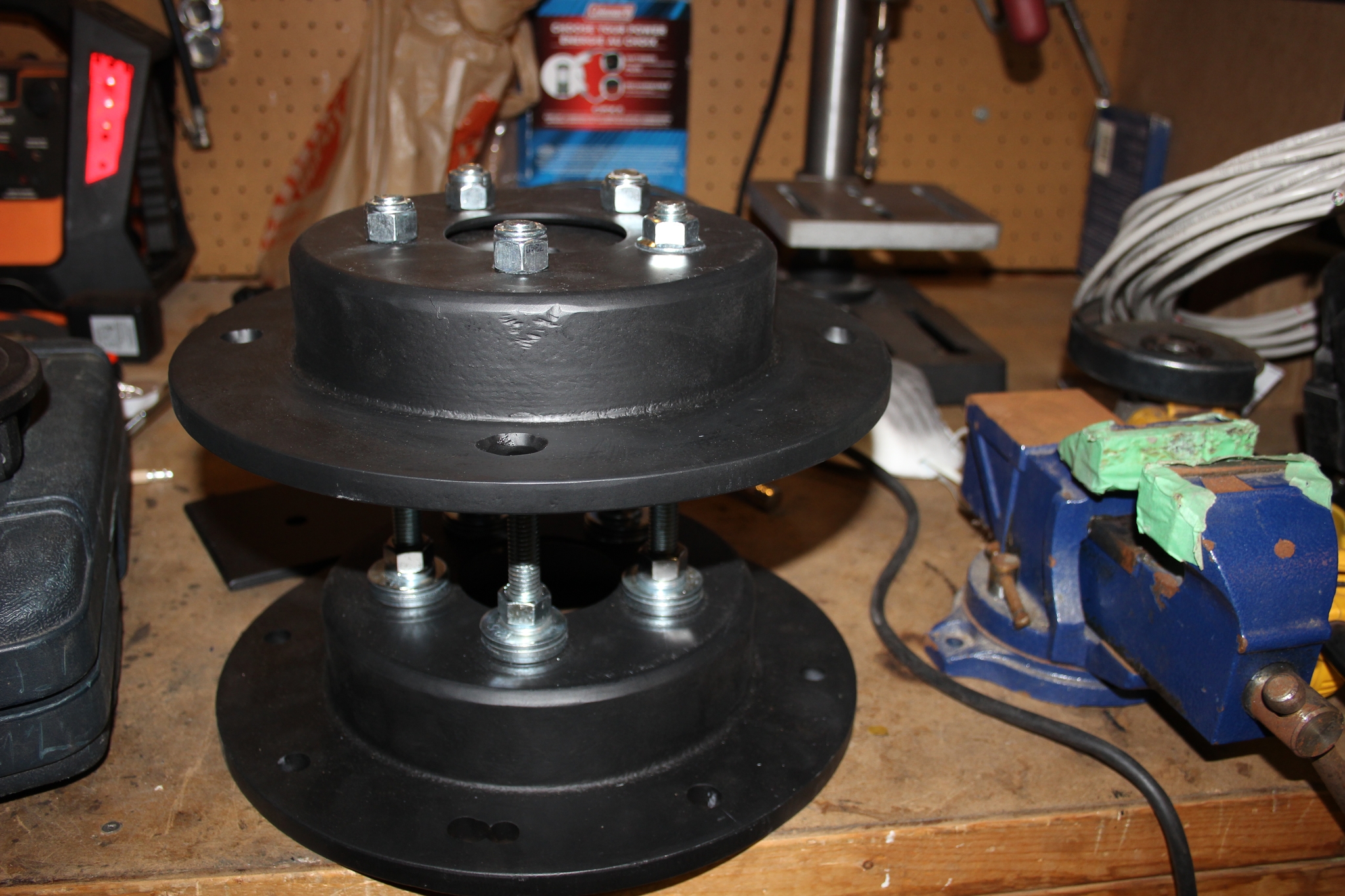
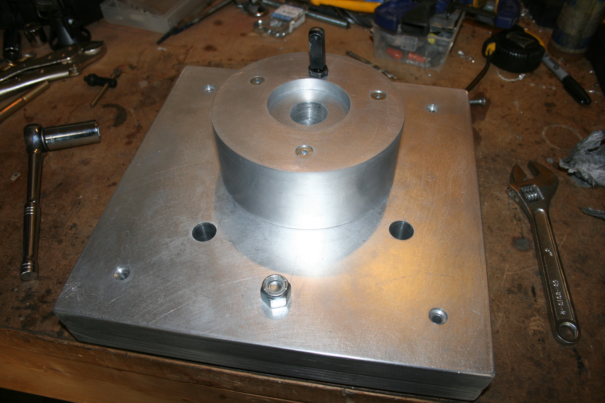
 52 Beutify it a bit and get rid of sharp edges to limit possible body damage at night if accidentally bumps into the adapter (head particularily). |
 53 All the individual pieces before putting it all together for the final time. |
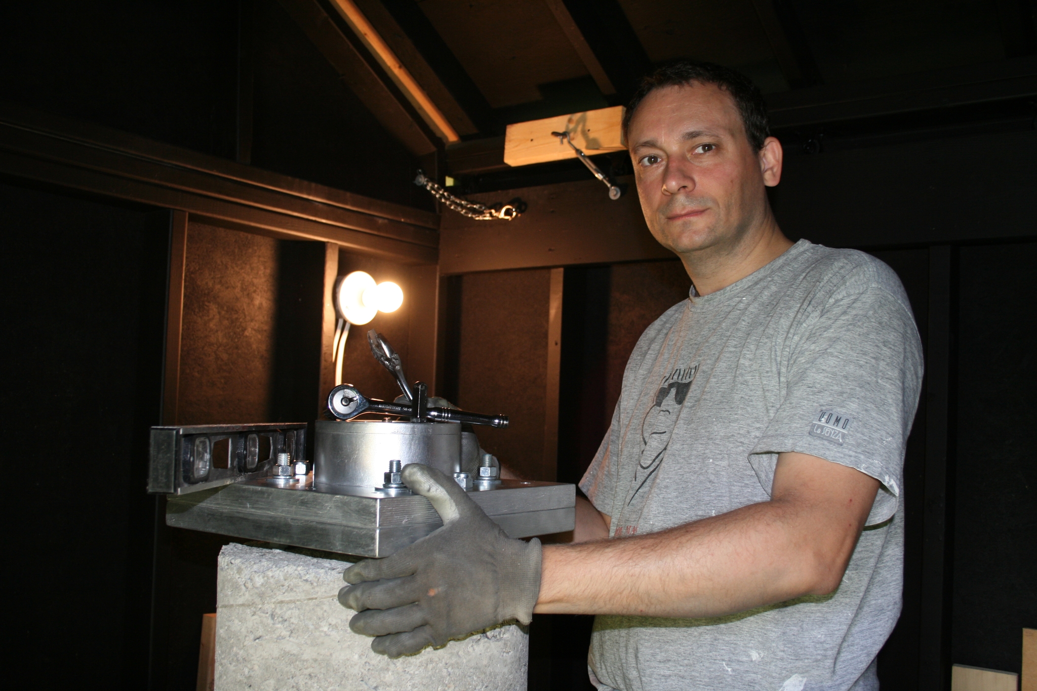
 54 Finally finished after many unforeseen complications (numerous to mention - all this looks easier than it actually was). |
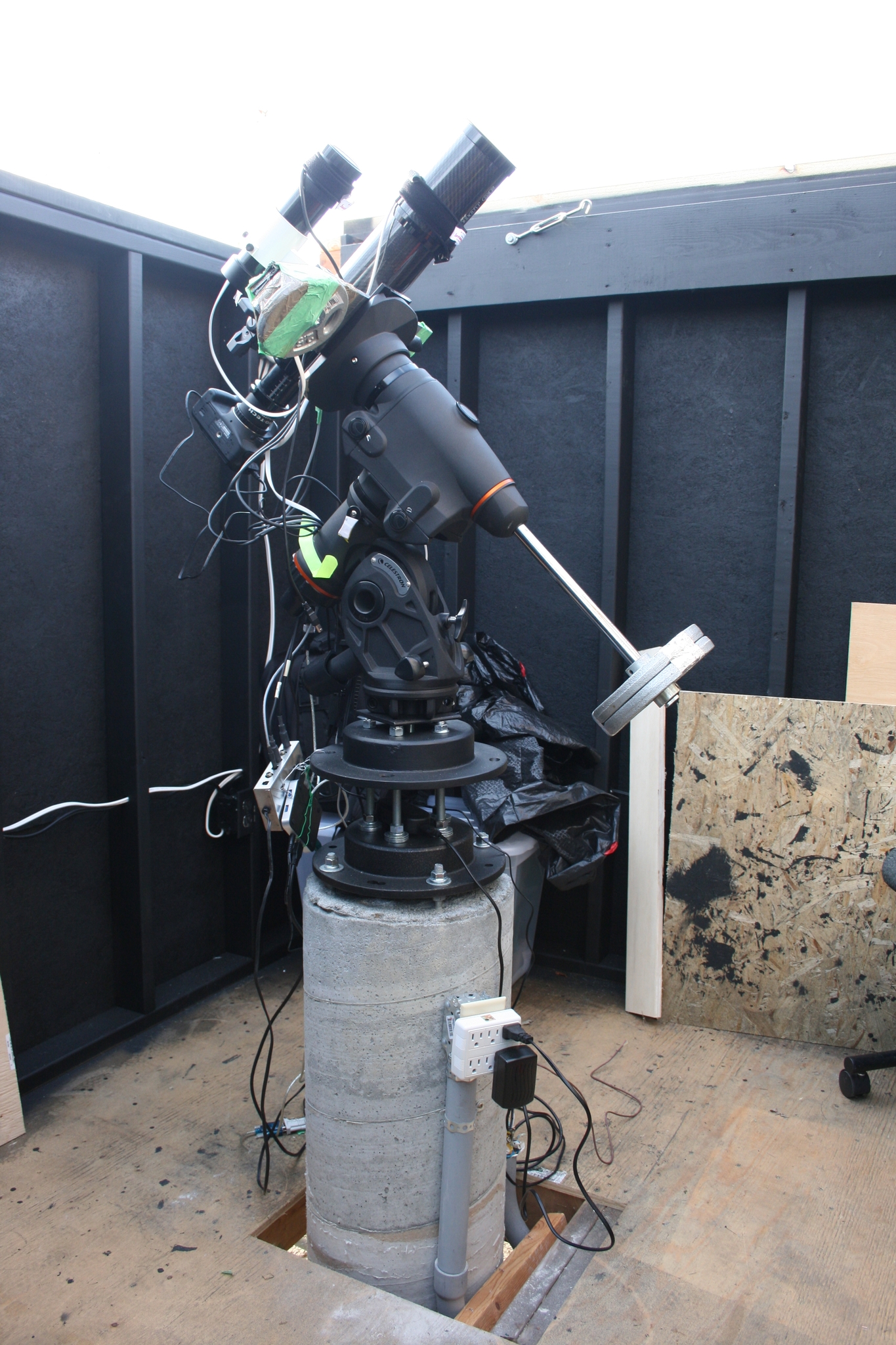
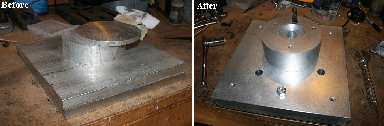 55 Before and after product. Tried adjusting it during a calbration night and this mount adapter is way better fitting, much smoother in operationa and thus way more accurate than the factory one! |
 56 Time to try it out. |
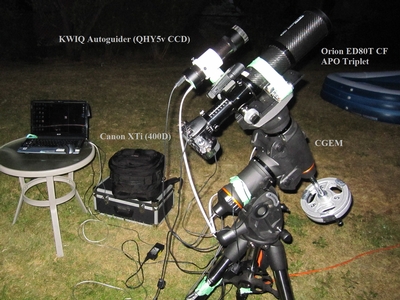
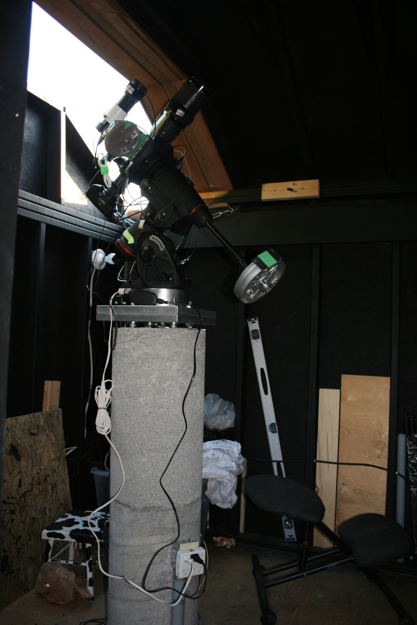 57 The rebuilt setup (wiring + weights still temporary until I figure out the setup is correct). |